


Technology – English
OilPure Technologies, Inc. is a manufacturer of an oil purification system for various industries. OilPure is an R&D based company which has developed its own proprietary patented oil purification technology to solve industrial lubricating oil problems. Our expertise is in Tribology and Lubrication Engineering. We are located in Kansas City, Missouri, USA.
OilPure Management Systems Co., Ltd. (OPMS) is OilPure subsidiary in Thailand. The technology was invented by Vichai in the US during the last 40 years in America. His development improves from the existing problems from other filtration technology and make it better. OPMS utilizes the art of Imagineering, TRIZ (Theory of Invention) to reinventing and differentiating the technology. We develop the Algorithm software program from Six Sigma technology for our software driven equipment.
OilPure technology is completely different from all conventional filtration and dehydration technology that are available in the market place as you will find out in our website. OilPure equipment utilizes IIOT4.0 and incorporates them into Wireless Remote Control and Remote Monitoring technology. OilPure equipment is also a Self Monitoring system. It diagnoses the internal filtration and send alarm message to alert operators.
There are many sensors using Analog Signal 4-20 mA with communication protocol of ModBus Network with Interactive Autonomous and ready to be responsive to any lubrication situation in either good or bad. So operator will be aware of the pending problems.
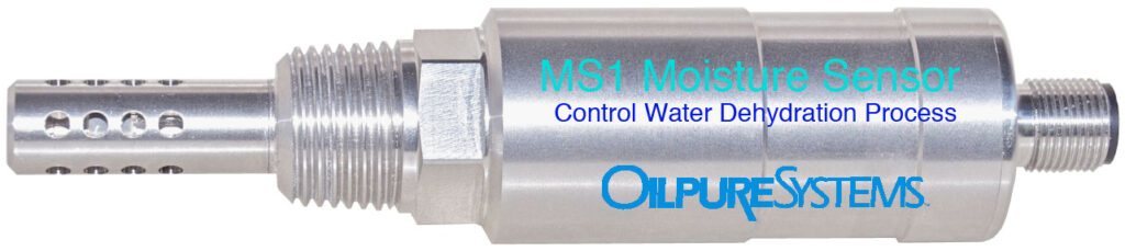
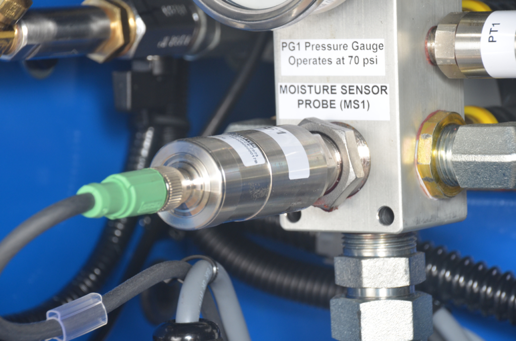
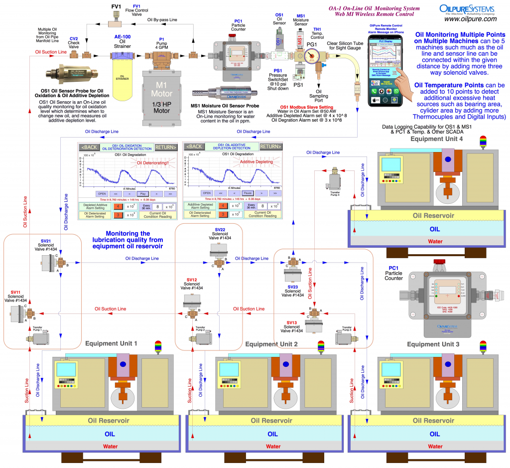
MS1 Moisture Sensor that can read Water Content in both ppm (parts per million) and % AW (Water Activity) as well as control the Vacuum Jet Water Dehydrating Process to assure that all wet oil will have less than 50-100 ppm of dehydrated oil output from OilPure equipment. MS1 is used in OilPure equipment such as VJ-50, VJ-100, VJ-150, VJ-300.
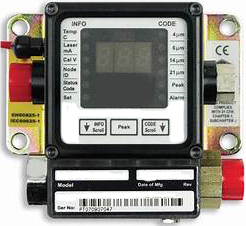
MS1 Sensor Port
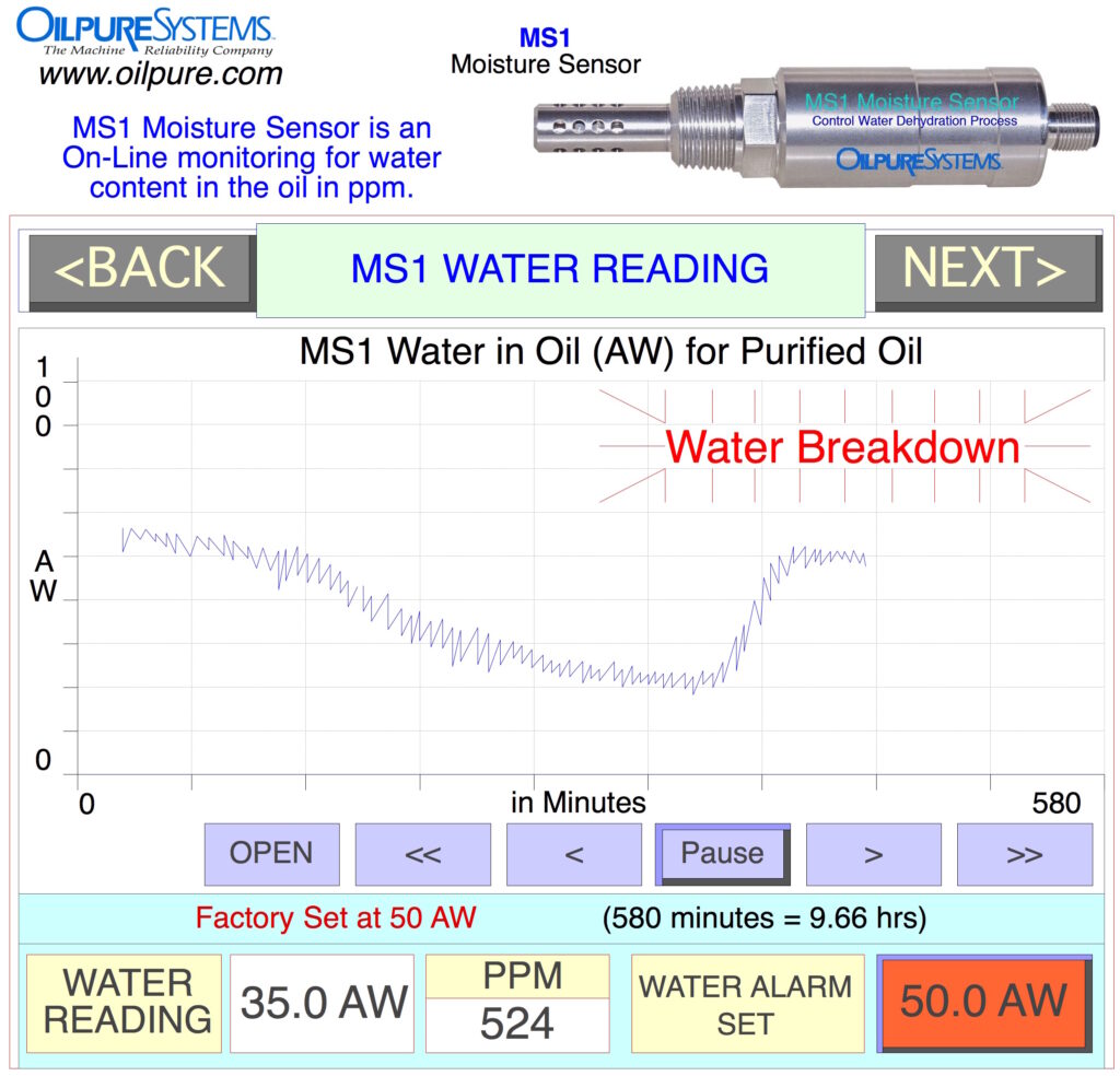
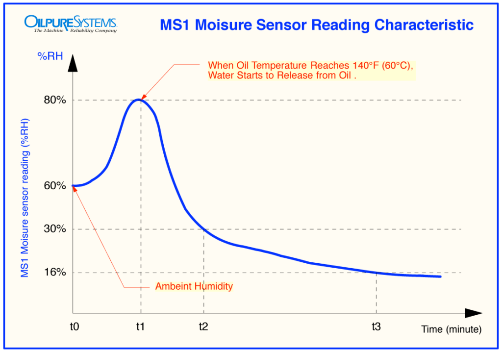
MS1 Moisture Sensor can read water in % AW (Water Activity) and ppm (Parts per million).
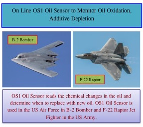
OS1 Oil Sensor has been using in US Air Force flying equipment such as B2 Bomber and F22 Raptor. This OS1 is sensing the chemical changes in the oil which has direct effect on Oil Oxidation and Oil Additive Depletion as its equipment first line of defense. Lubrication quality is measured in a Real Time and no need to send oil sample to laboratory and take too long for the oil test result.
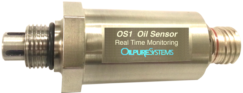
OS1 Oil Sensor uses in US Air Force flying equipment to measure chemical changes in the oil as CBM Condition Based Monitoring.
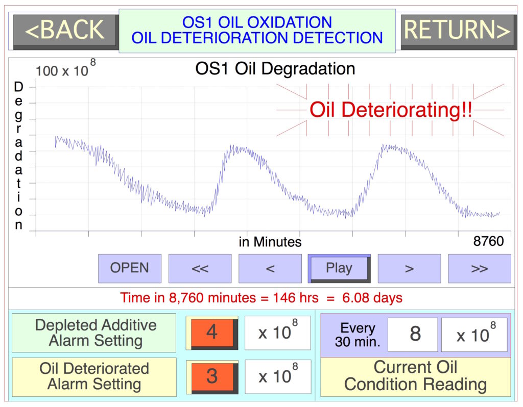
OS1 Oil Sensor reading display on Incremental changes in Oil Oxidation
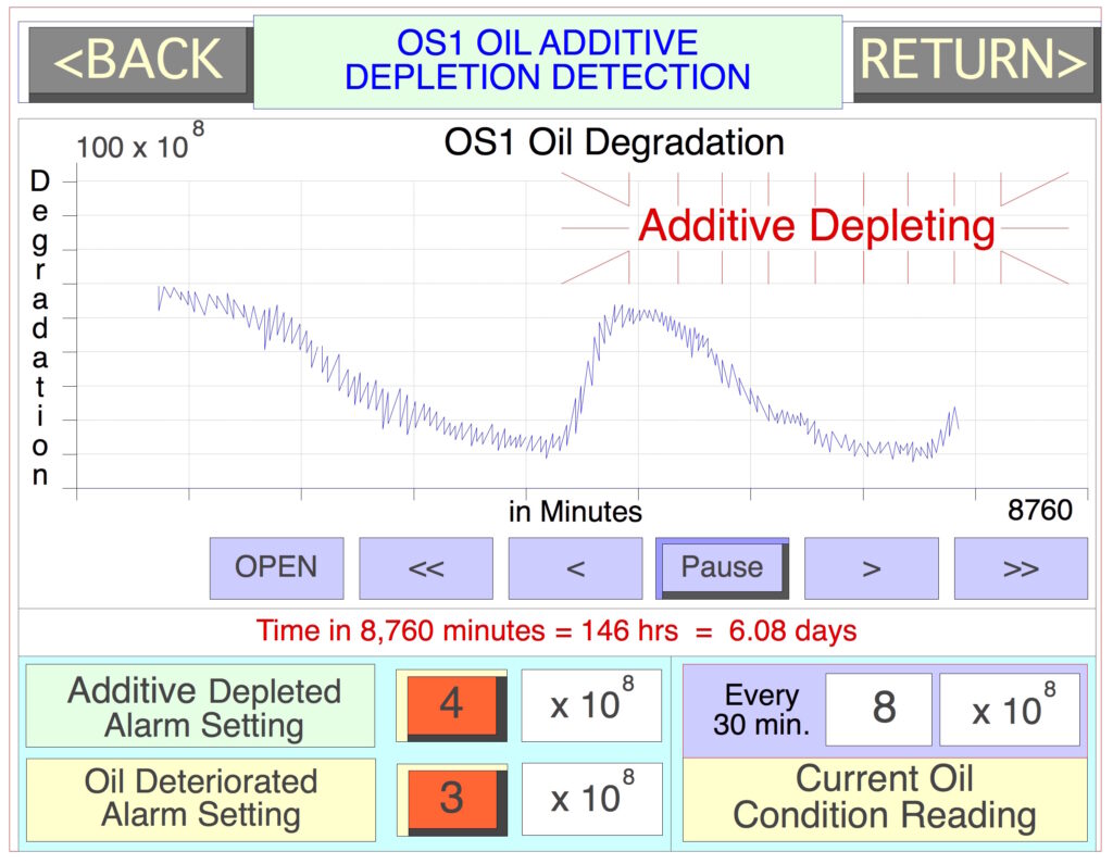
OS1 Oil Sensor reading display on Incremental changes in Oil Additive Depletion
WS1 Water Sensor detects Interface Layer between Free Water and Oil. When there is 3% – 80% water accidentally leaks in the lubricating system, WS1 in OilPure DT-100 Free Water Separator will separate and drains Free Water from the system.
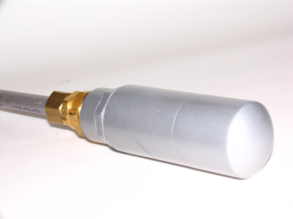
WS1 Sensor Probe
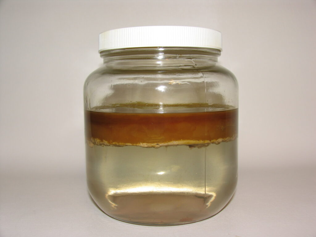
WS1 Detects interface layer between oil and free water.
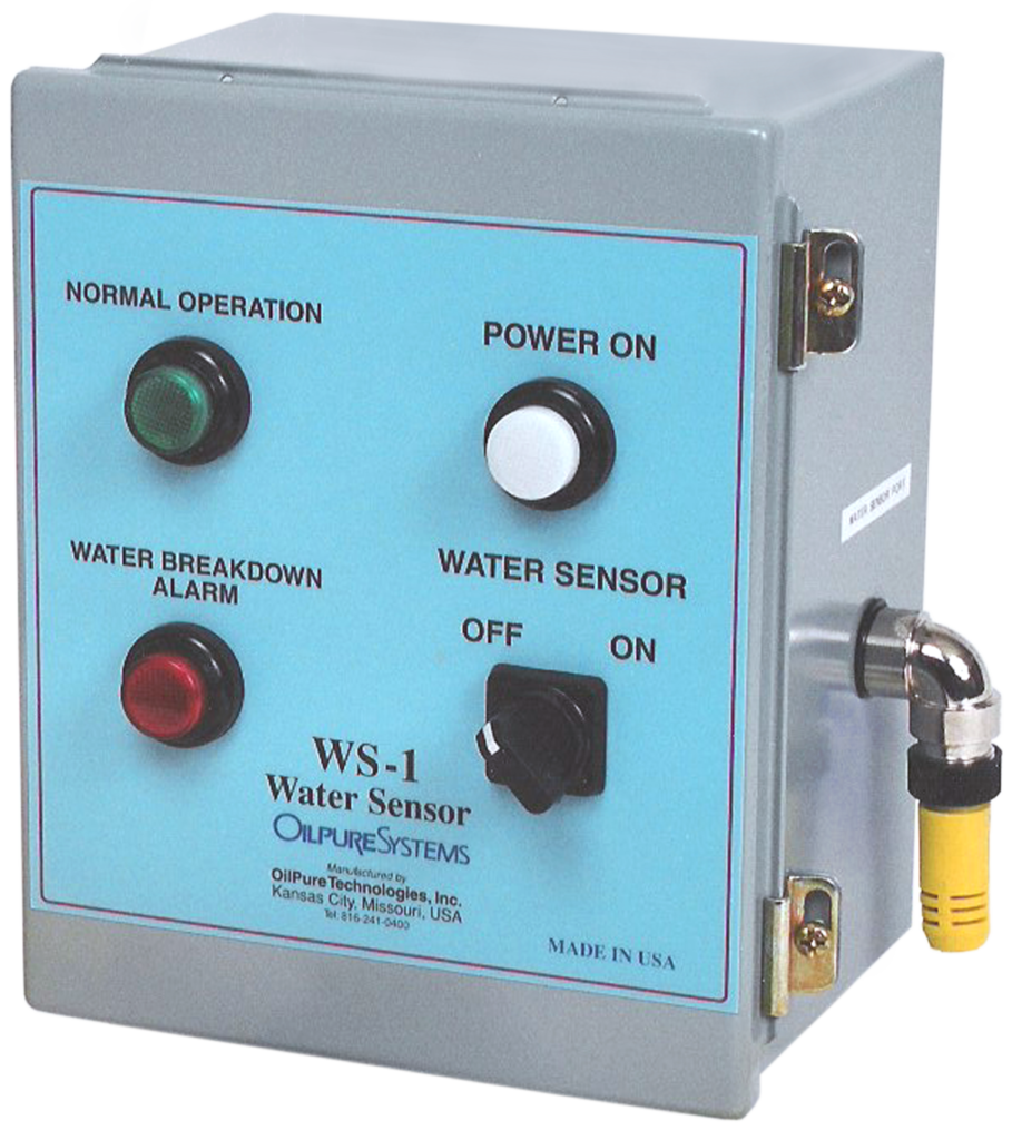
WS1 Controller
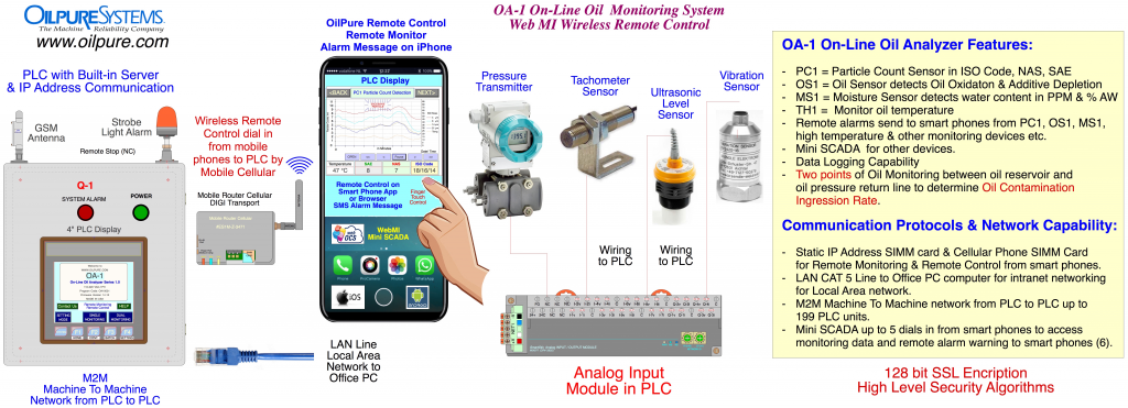
PC1 Particle Count Sensor reads particle count in ISO Code, NAS, SAE standards. PC1 is and On-Line Particle Count Monitoring system that can incorporate in OilPure Filtration Systems. Excessive particle alarm message can be sent from PLC directly to user smart phones by E-mail and SMS Text Messages.
PC1 Particle Count Sensor
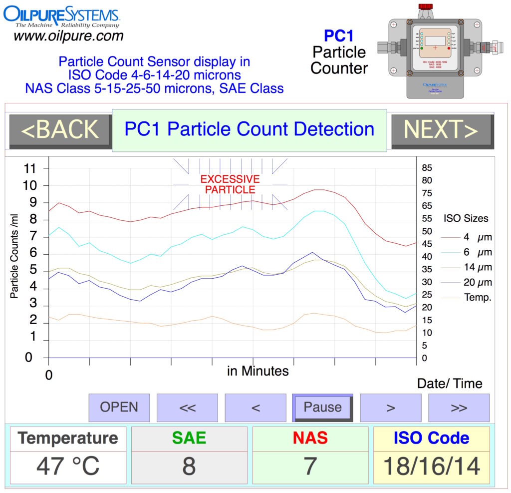
PC1 Particle Count Sensor reading display (ISO 4406)
UL3 Ultrasonic Oil Level Sensor is a non contact switch that controls oil levels in all OilPure equipment. It uses a sound wave to detect the oil level movement with very accurate reading.
OilPure is a US Defense Contractor for Black Hawk Helicopter Division in Corpus Christi, Texas, US Marine Corps in Albany, Georgia, and US Navy Nuclear Submarine, in Pearl City, Hawaii
US Army in Black Hawk Helicopter Division in Corpus Christi, Texas
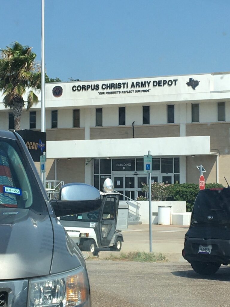
AST-50 Oil Recycling Machine is installed at Black Hawk Helicopter in Corpus Christi, Texas

OilPure works as a 3rd Tier Defense Contractor designing the Oil Recycle System for Synthetic fire resistant hydraulic MIL-PREF-83282, Mobil DTE26, Mobilfluid 424 for US Army.
US Marine Corps in Albany, Georgia
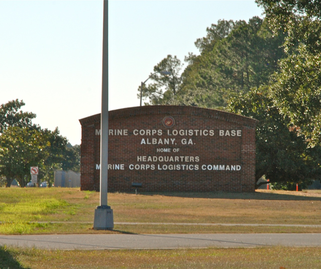
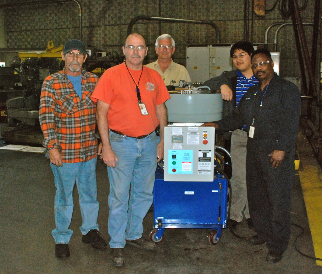
SS-50 Oil Purifier at USMC US Marine Corps, in Albany, Georgia
OilPure designs Transmission Recycle Fluid used in war equipment that was sent back for repair and overhaul at USMC.
US Navy Nuclear Submarine, in Pearl City, Hawaii US Navy, SDVT-1, ASDS
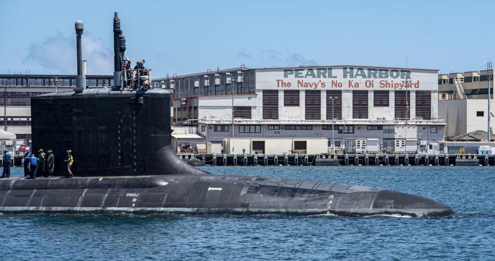
OIlPure designs Insulating oil Recycle System for motor in the Nuclear Submarine This special formulated Castrol Oil has only 6 drums in the world.
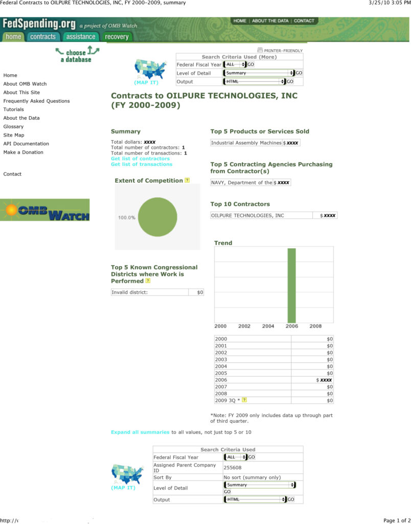
OilPure is a Supply chain in US Military.
PurePack Chemical Filter Technology
The PurePack TM is the purification medium in OilPure Systems technology. We prepare PurePack for you with an analytically determined mixture of chemical compounds in three or five layers. There are over 30 PurePack formula for various types of oil contamination. The composition of your PurePack is custom-designed to remove specific contamination from your dirty oil. PurePack material is 100% Food Grade material and 80%-100% are Biodegradable which is suitable for landfill or incineration disposal. While Conventional Oil Filter is made of Paper filter, is a One Size Fit All that can not remove Chemical Contamination from oil.
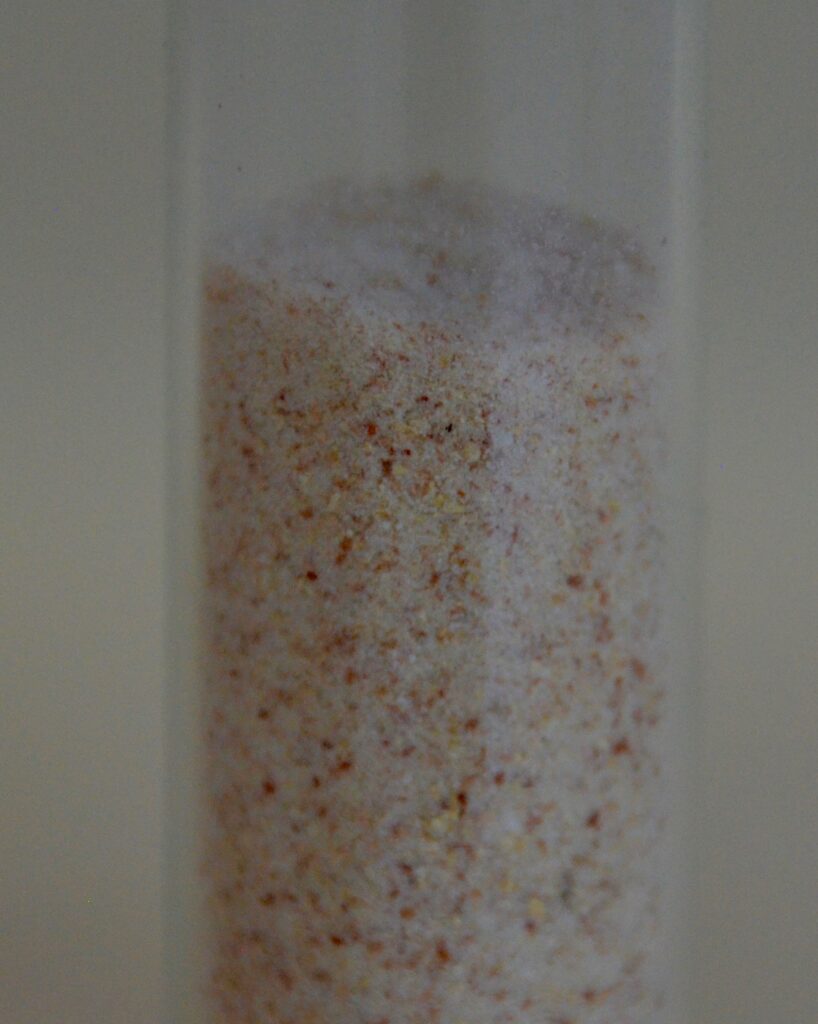
New PurePack – Food Grade Biodegradable 100% Organic Non Hazardous Materials

Spent PurePack does not only remove Solid Particle but also Absorb Water and reduce Oil Acidity as well as Oil Oxidation such as Ketone, Aldehydes, Alcohols Long Chain Hydrocarbon (Polymer).

Before & After Oils – PurePack Tester – Dirty oil is passing through PurePack media.
PurePack is made of very abrasive materials, powdery solid, organic materials that becomes porous crystal pack when wet with oil, trapping more solid oil contamination while the dirty oil is flowing cyclone like upward through PurePack media. The powdery solid forming in PurePack creates larger surface area for 30-40 times more Dirt Holding Capacity than conventional pleated cartridge paper filter media.
There is no Beta Ratio or Absolute Filtration Rating for PurePack filtration as PurePack itself is not a filter media to filter dirt from the oil. Various micron size dirts are trapping one another and becomes a cluster of dirt pack within the PurePack media bag. PurePack is simply creating the meshing environment to allow solid dirt to attract to one another and flock inside the PurePack media. The 10 or 3 or 1 micron dirt will traps the incoming 10 or 3 or 1 micron dirt while dirty oil is flowing through the PurePack media. PurePack marvelously allows Dirt to become the filter media to filter More Dirt at their own sizes.
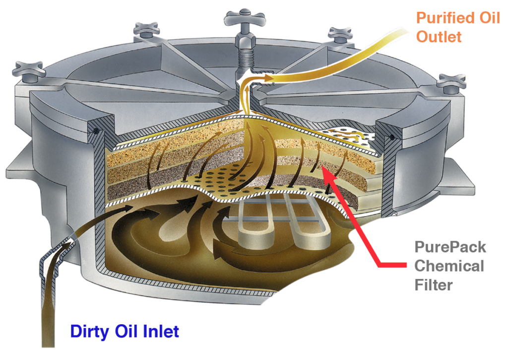
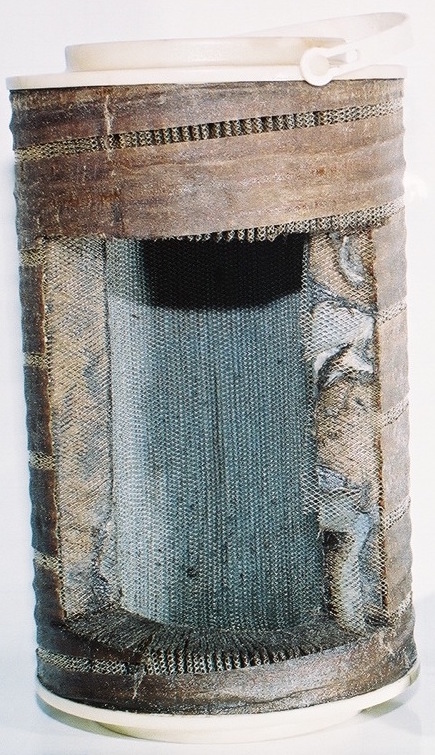
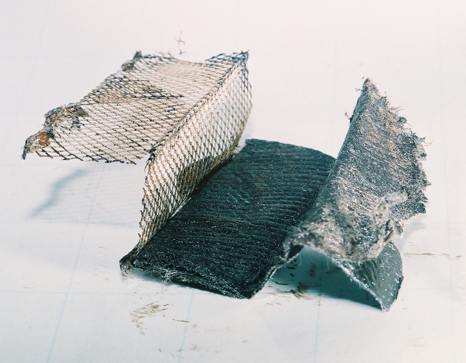
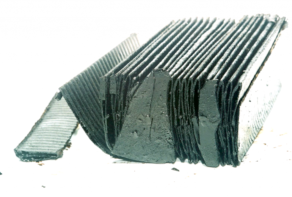
PurePack Cross Section
PurePack is contained inside Cotton bags.
PurePack media will become condensed as more solid dirt accumulates in the media, thus creating a cleaner oil flowing through. So the more number of oil passing through PurePack, the higher oil cleanliness becomes or becomes cleaner oil with more oil passing through. More oil passes will fabricate a better ISO Code or NAS Oil Cleanliness for purified oil.
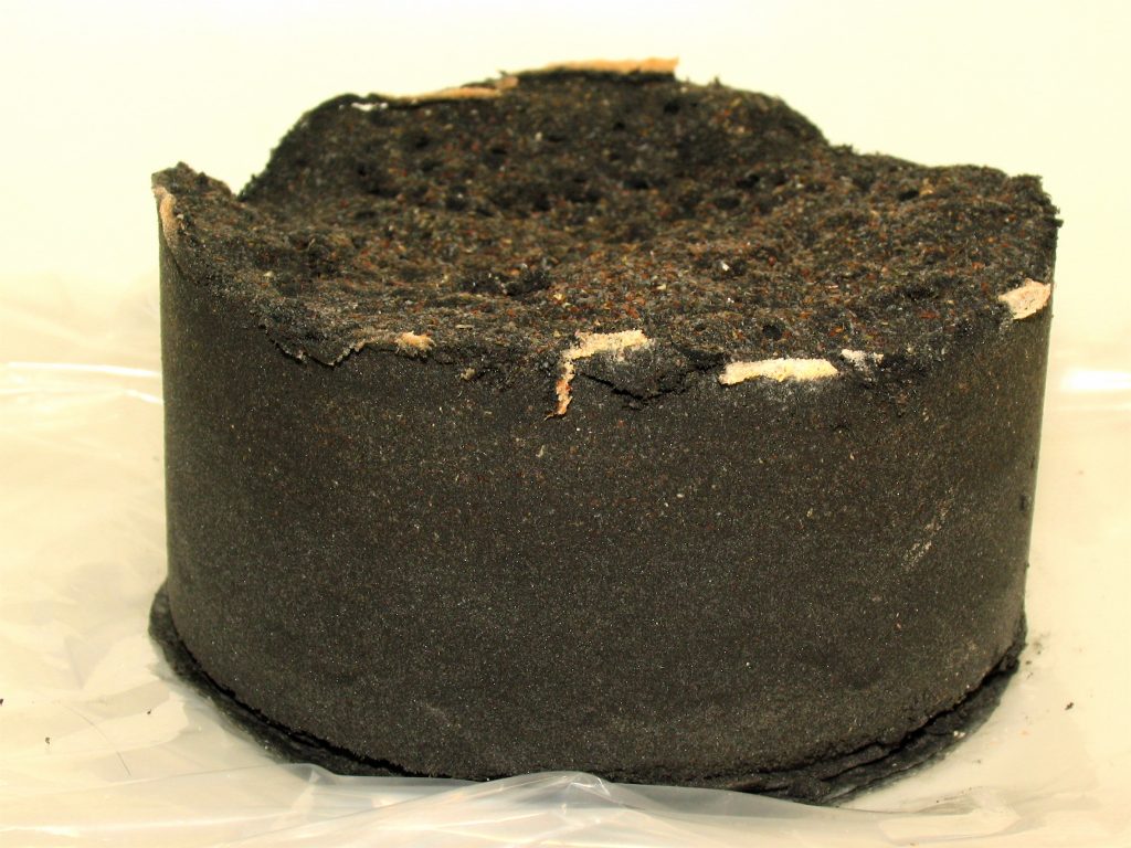
Spent PurePack clusters solid dirt from 1 to 50 micron size and still maintains much High Dirt Holding Capacity for oil filtration, and still not clogged prematurely.
Dirt Holding Capacity in conventional Pleated Cartridge Paper Filter depends of the area of paper and number of pleats so high dirt content will jam the paper surface as it has small amount of Surface Area available.
PurePack materials are 100% Organic, natural element so there will be no Electrostatic Charge occurred in the flowing oil as compared to other conventional pleated paper materials. This Electrostatic charge generates Concurring Oil Oxidation in the lubricating oil which most oil users have no idea how this oil oxidation came from.
Most low micron pleated cartridge paper filters are one of sources of Oil Oxidation.
6 Micron filter element is made of nylon, polyester, plastic materials that are a cause of oil oxidation.
Electrostatic charge swells screen plastic on filter media causing friction between oil and nylon plastic.
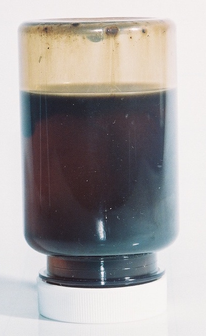
Varnish from electrostatic charge in the oil sample
Excessive carbon from hydrocarbon oil built up on filter surface. These are carbonyl materials that prematurely clogged filter element.
Internal corrosion on hydraulic part surface caused by electrostatic charge in the oil.
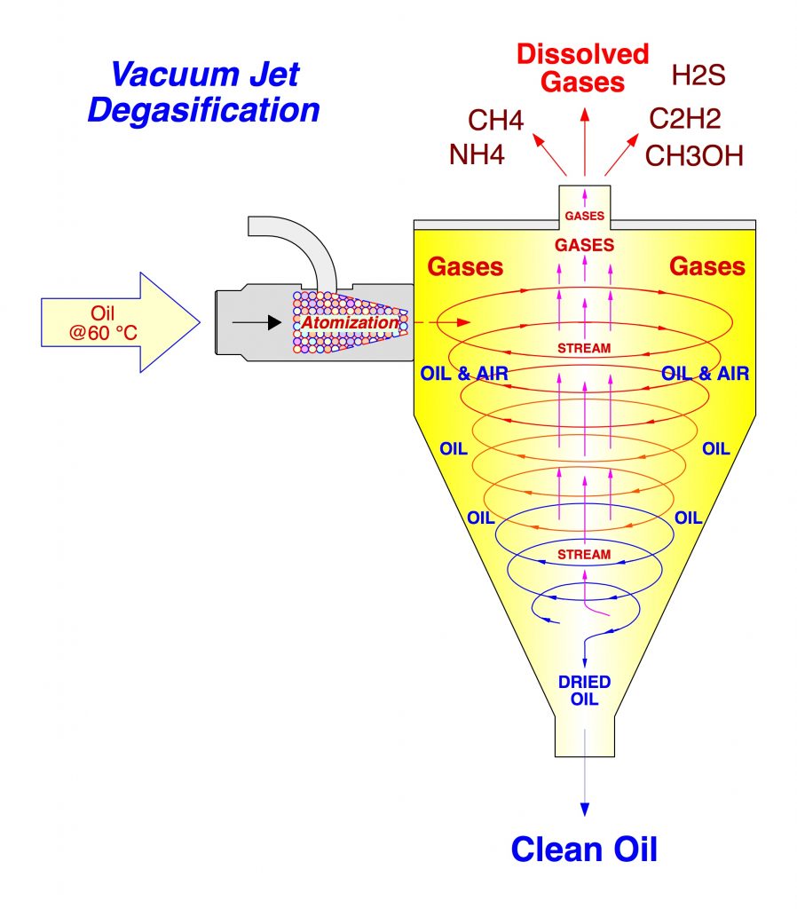
Vacuum Jet Dehydration Technology
acuum Jet Dehydration Technology has been invented by OilPure more than 25 years ago learning from the existing problems in Conventional Vacuum Distillation that can not ultimately solve water dehydration in oil. This Vacuum jet Dehydration technique has been a new theory of Non Vacuum for water removal in the oil by trying and error for 5 years to perfect this technology.
How Vacuum Jet Technology Works?
Vacuum Jet Dehydration applies oil pressure at 70 psi and oil temperature at 140 °F mixing with atmospheric air to atomize through nozzle to create oil & water aerosol mixture, swinging through a cyclone separator.
The air/ oil mixing action forms the fluid mixture into aerosol as it enters the special design cyclonic separating tanks. At the right oil temperature any atmospheric air (even humid air) will increase its velocity while absorbing water from oil in the cyclonic separating tank. Water was previously in a liquid state, when it dissolves in the dirty oil. After the aerosol is mixed with air, water changes from liquid state to vapor state in the cyclonic separating tank. The cyclonic forced air will carry dissolved water to the upper steam and allow dried oil to fall to the bottom.
Vacuum Jet Dehydration incorporates MS1 Moisture Sensor to control water dehydration process so water content from 2,000 – 10,000 ppm from incoming dirty oil will be removed down to 10-50 ppm before dried oil is discharged from Vacuum Jet Dehydrator.
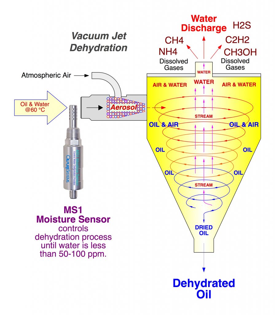
Vacuum Jet Technology is capable of not only removing Dissolved Water, but also removes Dissolved Gases that have decomposed in the lubricating oils.
MS1 Moisture Sensor is controlling the water dehydration process to assure that the incoming 2,000 – 10,000 ppm of water will be removed down to 10-50 ppm before the dried oil is discharged from the dehydrator.
Water changes from Liquid Stage into Vapor Stage at 60 °C during dehydration. This process saves heating energy for water dehydrating process.
Dissolved Gases such as CH4OH Methanol in Biodiesel, CH4 Methane, C2H2 Acetylene, H2S Hydrogen Sulfide, NH4 Ammonia, CO2 Carbon Dioxide etc. will be atomized and inflated with dissolved water, rising from oil in the cyclone separator. NH4 Ammonia dissolved gas in refrigeration oil can be degassed by Vacuum Jet Dehydration as well.
Advantages of Vacuum Jet Dehydration Technology over Conventional Vacuum Technology:
- Vacuum Jet Dehydration can remove water from high viscosity gear oil up to 600 ISO grade viscosity while Vacuum distillation barely handle ISO 220 oil viscosity grade. Very little amount of water can be pulled out so it has to heat the oil temperature to 170°F – 175 °F to get more water out but risking the built up of Oil Oxidation and oil breakdown.
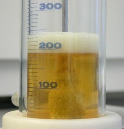
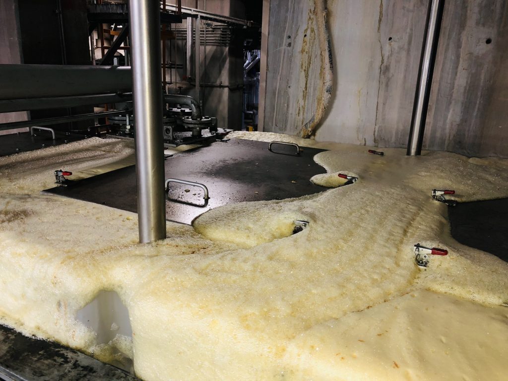
- When water content is over 3% (30,000) ppm of water in the oil reservoir, there will be excessive oil foaming occurred in the oil reservoir. This foaming will escape into vacuum pump and condenser causing vacuum pump premature damages and repair. So Vacuum Switch is energized to reduce vacuum level from 21-24 Inch/Hg down to 16-18 Inch/Hg in order to bring down excessive foaming in the vacuum chamber. This causes inefficiency in water removal for Vacuum Distillation. Most of the time this doesn’t work.
- Vacuum Jet Technology is also capable of degassing the Dissolved Gases such as CH3OH Methanol in Biodiesel, CH4 Methane, C2H2 Acetylene and H2S Hydrogen Sulfide in Transformer oil. Vacuum Jet atomizes these Dissolved Gases as well as water which has similar affinity to be ejected from cyclonic separator.
- Vacuum Distillation also removes these Corrosive Dissolved Gases through vacuum pump and condenser, causing component corrosion and premature failure to a short life vacuum pump.
- Vacuum Jet Dehydration is low or no maintenance using positive displacement gear pump to increase oil pressure. This gear pump has a 5 year MTBF (Mean Time Between Failure). Vacuum Jet Dehydrator is designed to run on a non stop 24 hours/ 365 days basis. Nozzle eductor in Vacuum Jet is a self cleaning and will automatically clean itself every 20 cycles. Therefore, there is no oil line clogging for maintenance.
Vacuum Jet Degasification Technology
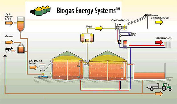
Degasification of CH4, H2S Gases from Diesel Engine Oil from Landfill & Biogas Power Generating Engines
Vacuum Jet is also capable of degassing the CH4 Methane, H2S Hydrogen Sulfide gases (Low Molecular Weight Gases) from Diesel Engine Oil in Gas Turbine Generator such Caterpillar, Cummins, GE, Jenbacher Diesel Gas Engine from Biogas and Landfill Natural Gas generation. These corrosive gases reacts with base oil and increase oil acidity TAN (Total Acid Number) in the oil, consequently depletes oil additives such as TBN Additive.
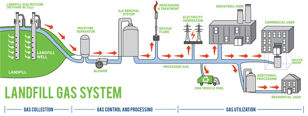
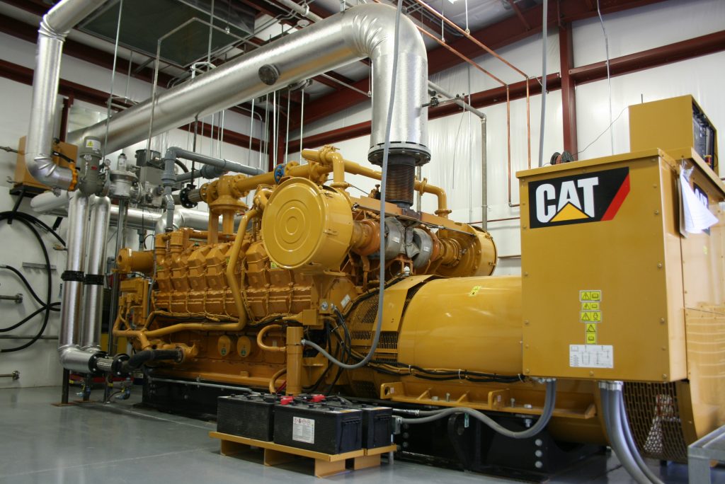
Diesel Gas Turbine Engine
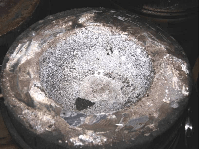
CH4, H2S, CO2 Gases in lubricating oils came from the decomposition of hydrocarbon in service for a long period of time. These CH4 Methane Gas reacts with Silicon Dust from the Landfill Well and forms a by product called “Siloxane” having particle size of 0.5-3 microns. Siloxane is very Abrasive and has High Hardness Value which cause Excessive Wear in the diesel engine components such piston ring, cylinder and bearings. This premature engine component failure and a short lubrication life is caused by these corrosive gases.
Vacuum Jet Degasification is capable of removing the decomposed gases from Landfill and Biogas Turbine Engine oil causing Diesel Engine corrosion from Siloxane that shortens the oil changing interval to 500 hours, rather than 2,000-3,000 hours of normal oil life.
Solution to this engine oil corrosion is to degas CH4, H2S Gases from Diesel Engine Oil with Vacuum Jet Degasification and filters the oil through PurePack media that can remove Siloxane having 1-3 microns. TC-8 High speed centrifuge may need to remove sludge that came from Excessive TBN – Oxidation by products. This excessive sludge can cause the premature clogging filters.
Vacuum Jet Degasification can removing the following gases:
- CH4 Methane
- C2H2 Acetylene
- NH4 Ammonia
- C6H6 Benzene
- C5H12 Pentane
- C3H8 Propane
- H2S Hydrogen Sulfide
- CO2 Carbon Dioxide
- C2H4 Ethylene
- C3H6 Propylene
- HCL Hydrogen Chlorine
- CH3OH Methanol
These Dissolved Gases are small quantity in most lubricating oil, but has enough to cause a premature vacuum pump failure in the Vacuum Distillation unit. Most user of Vacuum Distillation has been repaired their vacuum pump on a regular basis but have no idea why vacuum pump fails very often.
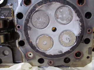
Siloxane Wear on Cylinder
Siloxane Wear on Cylinder
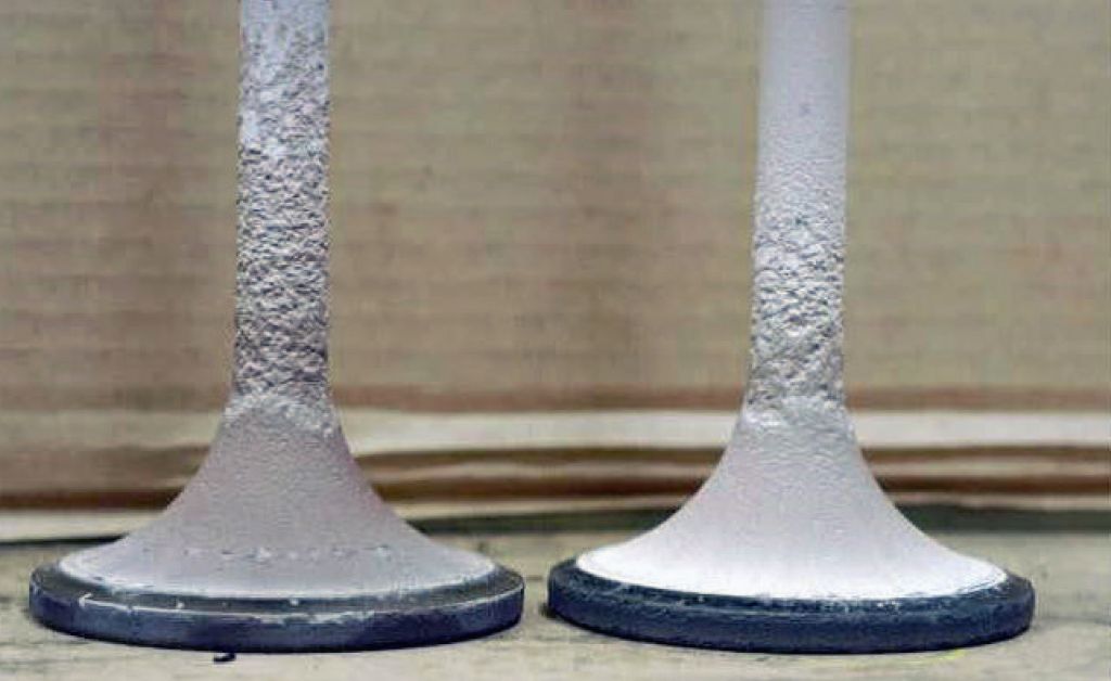
Siloxane Wear on Valve
Siloxane Particle is very small size of 1-3 microns while best OEM oil filter can only filter up to 50 microns level. Siloxane will keep accumulate in the lubricating oil so the oil company has to increase more TBN additive to 10-14 points to disperse this minute particle and emulsify them into the oil, the same way that Carbon Black is dispersed in the oil. However, this is really not the way to solve the Siloxane problem in engine oil.
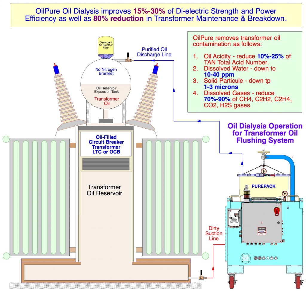
Sub Station Transformers – Degasification of CH4, C2H2, C2H4, CO2, H2S Gases
Sub Station Transformer such as LTT (Transmission Line Transformer) or OCB (Oil Filled Circuit Breaker) are Distribution Transformer and LTC (Load Tap Changer) is Power Transformer. Distribution Transformer having oil reservoir size from 150 – 500 gallons and Power Transformer having oil reservoir size from 3,500 – 7,500 gallons are all having oil contamination problems as described followings:
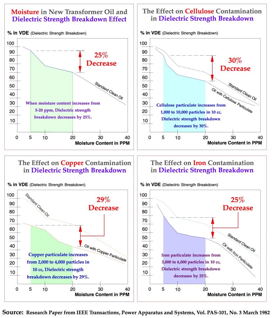
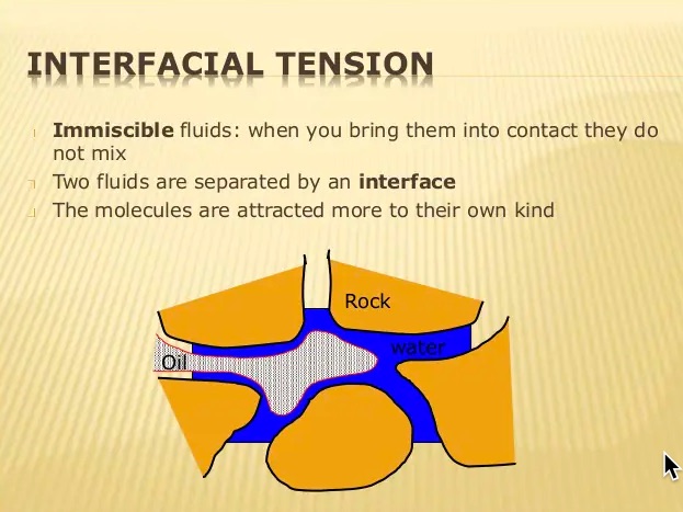
- Dissolved Water is more than 50 ppm will cause the reduction of Di-Electric Strength and IFT Interfacial Tension values.
- Dissolved Gases such as CH4 Methane, H2S Hydrogen Sulfide gases, CO2 Carbon Dioxide has impacted on transformer corrosion as well as transformer blow up during the Peak Hour.
- Oil Acidity – TAN (Total Acid Number) has direct effect on Di-Electric Strength value.
- Minute Solid Particle size from 1-3 microns from Copper, Iron and Cellulose occurring in transformer oil have direct effect on Di-Electric Strength value. Especially Cellulose becomes decomposed and form Polymeric substance in the oil as well as generates CO2 and CO gases in the transformer oil.
Vacuum Jet Degasification can remove these Corrosive Dissolved Gases from transformer oil in an attempt to improve 15%-30% of Di-Electric Strength as well as reduce over 80% of transformer maintenance and breakdown. This gases will have no corrosion effect on Vacuum Jet Degasifier pump or process as compared to conventional Vacuum Distillation Process.
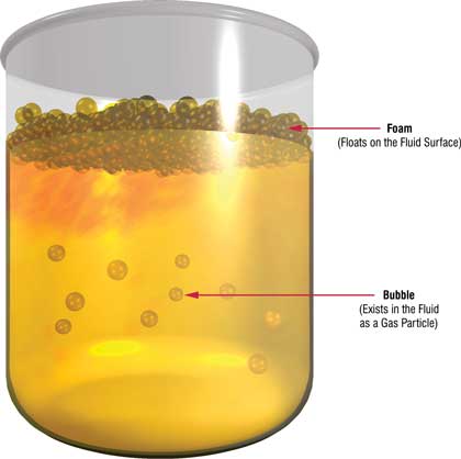
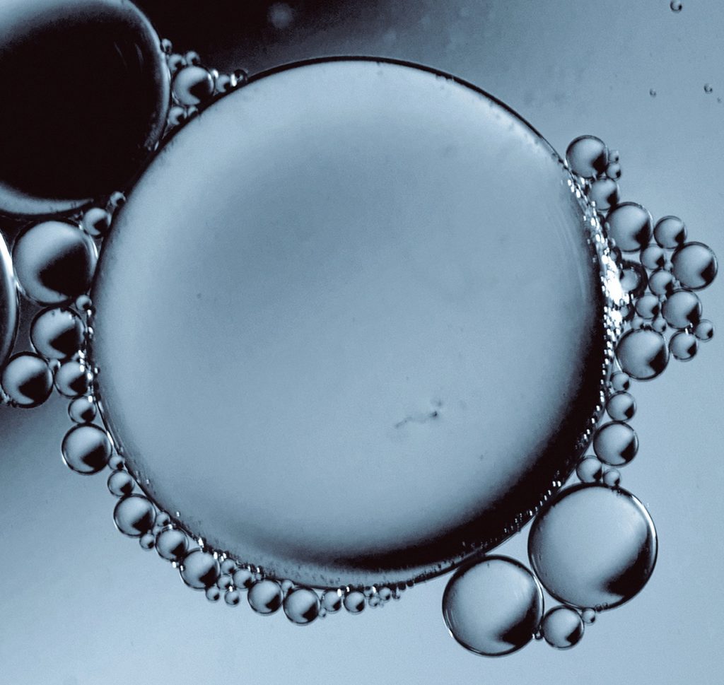
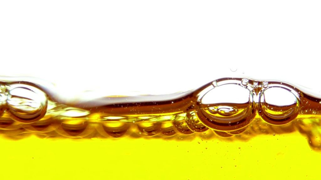
Dissolved Gas – v.s.- Entrained Air – v.s.- Air Bubble Removal from Oil
While Vacuum Jet Degasification is capable of removing Dissolved Gases that is compressed in the oil, not visible by the eyes. There are two other gases or air in the oil that also cause foaming problems; Entrained Air and Air Bubble which both of them are visible by eyes. These bigger gases or air come from oil pressure drop in the oil flow causing small gases or air to inflate and become air foam floating in the oil reservoir. This phenomenon occurs under Bernoulli Principle when air is under Cross Sectional Area while Velocity of Gas increases.
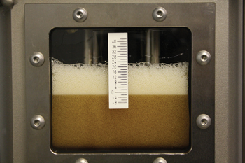
Entrained Air & Air Bubble in Oil Reservoir
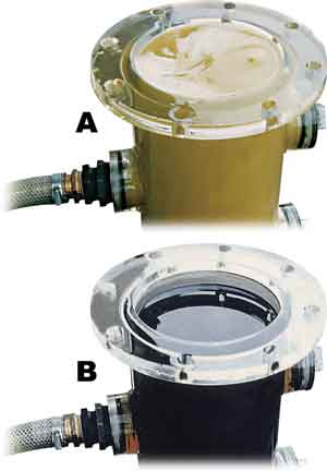
Entrained Air is removed.
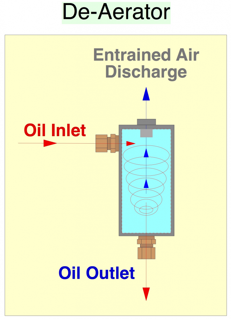
De-Aerator Technology
DA-3 OilPure De-Aerator is designed to remove Entrained Air & Air Bubble from oil. These air foaming will breakdown the Oil Film on metal surface during the lubricating process. Air Foaming will reduce Surface Tension and Interfacial Tension (IFT), thus repelling oil film to move away from metal surface. So metal starts to contact other metal surface with no oil film in between. This is just like running the machine with no lubricating oil film sticking on surface metals when oil foaming is occurring in the oil.
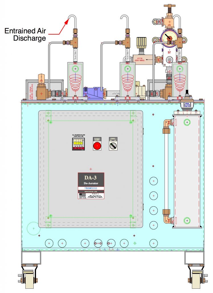
DA-3 Aerator Unit
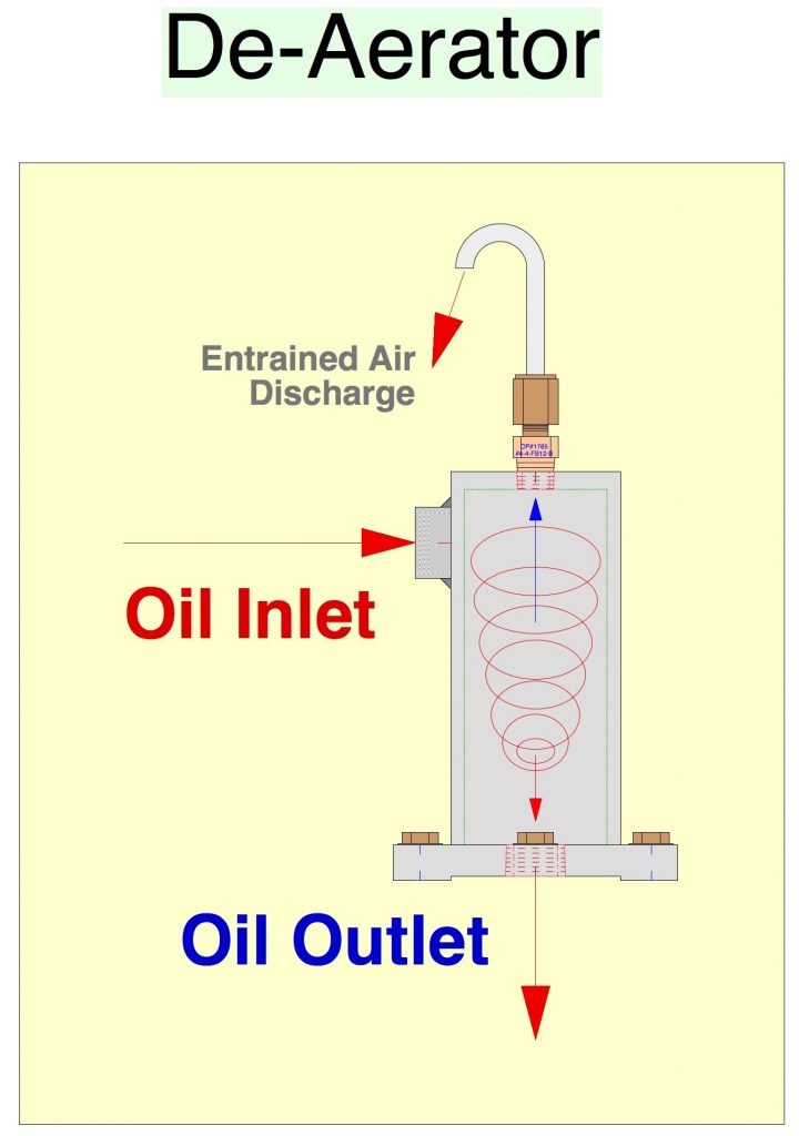
How De-Aerator removes Entrained Air from oil.
DA-3 De-Aerator Unit from OilPure is good to remove Entrained Air & Air Bubble from oil reservoir size up to 1,000 gallons.
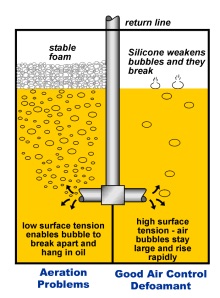
To solve Dissolved Gases problem is different from solving Entrained Air due to their different Foaming Characteristic. Entrained Air will accumulate into large Air Bubble and become Stable Foam. This is most likely caused by Defective Base Oil and we are not be able to solve this foaming with lubricating technology such as adding Anti Foaming Additive, but replacing with new Base Oil.
The Difference among Dissolved Gases vs Entrained Air vs Air Bubble
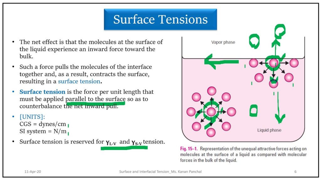
Air Foaming is formed due to 2 different tension forces as described follows:
- Surface Tension is molecular force between oil film surface and metal surface that is hold between several oil molecules. This oil film can be described in slippy hand. We can not wipe the oil from our hand. We have to use soap and water to reduce surface tension of oil film and rinse them out with water. Soap is acting as Surfactant to breakdown surface tension between oil film and skin.
- Interfacial Tension (IFT) is molecular force between liquid or oil of how they pull one another so the oil is holding together as liquid while they are flowing. When Interfacial Tension decreases, air foaming start to pull in between oil molecules and becomes Entrained Air or Air Bubble depending on the sizes.
- Dissolved Gases
Dissolved Gases is very small, soluble of air foaming dissolved and emulsified in the oil, not visible by eyes. The gases in positive displacement pump was mostly compressed from suction side and decompressed from the discharge side of the pump with oil pressure and heat in the oil. Dissolved gases usually have little effect on lubricating process when they are dissolved in the oil. Dissolved Gases can be compressed in small foam or decompressed into larger foam during lubricating process. Larger foam definitely can cause Cavitation as it will reduce surface tension from oil film and metal surface, thus affecting excessive wear on components.

Dissolved Gases
Anti Foaming Additive is normally used in the oil to control the Surface Tension and Interfacial Tension that prevents air foaming not to easily form in the oil. This Anti Foaming Additive is made of Silicone that is very sensitive to oil oxidation. It is the first one to go for additive depletion occurred from oil oxidation.
Excessive Stable Foam is caused by oil contamination such as Water, Oxidation or Oil Acidity that reduces Surface Tension in the oil.
Dissolved Gases can be removed from oil by Vacuum Jet Degasification.
2. Entrained Air
Entrained Air is a larger air foaming, mostly inflate from Dissolved Air or Gases when oil is agitating or turbulent flow. Large air foam usually starts from the bottom and rise to the top becoming the Tendency Foam within 5 minutes. This is considered as normal.
Entrained Air caused by oil contamination such as Water and Oxidation or Higher Oil Acidity that reduce both Surface Tension and Interfacial Tension.
Entrained Air can be removed by DA-3 De-Aerator from OilPure. Anti Foaming Additive that is made of Silicone, can be refortified into the clean oil only. This will help to control a better Tendency Foam in the oil. However, this can be done only when oil is free of water and oxidation.
If Tendency Foam does not disappear soon, it will keep forming the Stable Foam which causes more damages to the machine.
3. Air Bubble
Air Bubble is normally a larger foam that is inflated from Dissolved or Entrained Air. It starts after Anti Foaming Additive has been depleted and oil has been agitated for a long period of time. This Air Bubble will not easily disappear and can become the Stable Foam that Air Foaming can explode from the manhole tank of oil reservoir.
This Air Bubble can be removed by DA-3 De-Aerator from OilPure with the help of Anti Foaming Additive refortification.
Except when Air Bubble becomes Stable Foam that has a root cause from Defective Base Oil from refinery plant. DA-3 De-Aerator can only alleviate the foaming situation with Anti Foaming Refortification, but will not solve Air Bubble in Stable Foam problem.
There are 6 causes of Air Foaming in the Oil as listed followings:
- Oil Contamination such as Dissolved Water and Oil Oxidation occurring during the overheated oil for a long period of time.
- Depleted Anti Foaming Additive can affect poor Surface Tension and causes excessive Air Foaming.
- Excessive Surfactant infiltrates in the oil reservoir. This can cause excessive foam.
- Poor Machine Design that has plenty of dead zone from 90° angle pipe corner. Fluid Flow can cause excessive heat within the corner of pipe. This causes pump cavitation in hydraulic system. It is an poor OEM design problem.
- Defective Base Oil from refinery that has periodical poor quality control problem, can cause an unresolved foaming problem. Defective Base Oil has incompatible with additives and unable to become homogeneous showing a white gluey color in the oil. Most oil blenders will add more Dispersant Additive to solve this homogeneous problem. But it is only masking the problem.
- Defective Base Oil from refinery that has long term poor quality control problem. The whole production lot of base oil has been defective. By over dosing Dispersant Additive will have the side effect and more air become the Air Release Issue that creates Large Stable Air Foam. This Large Stable Foam does not act like normal air foaming but become a chuck of liquid foaming that expands and explodes out of oil reservoir from the top manhole
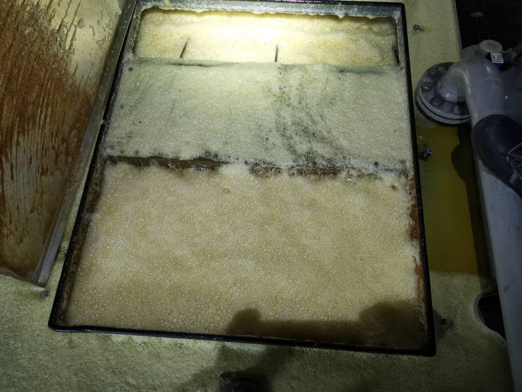
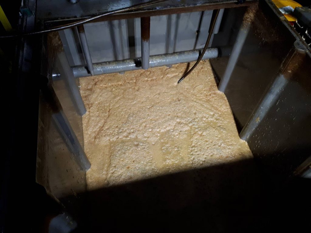
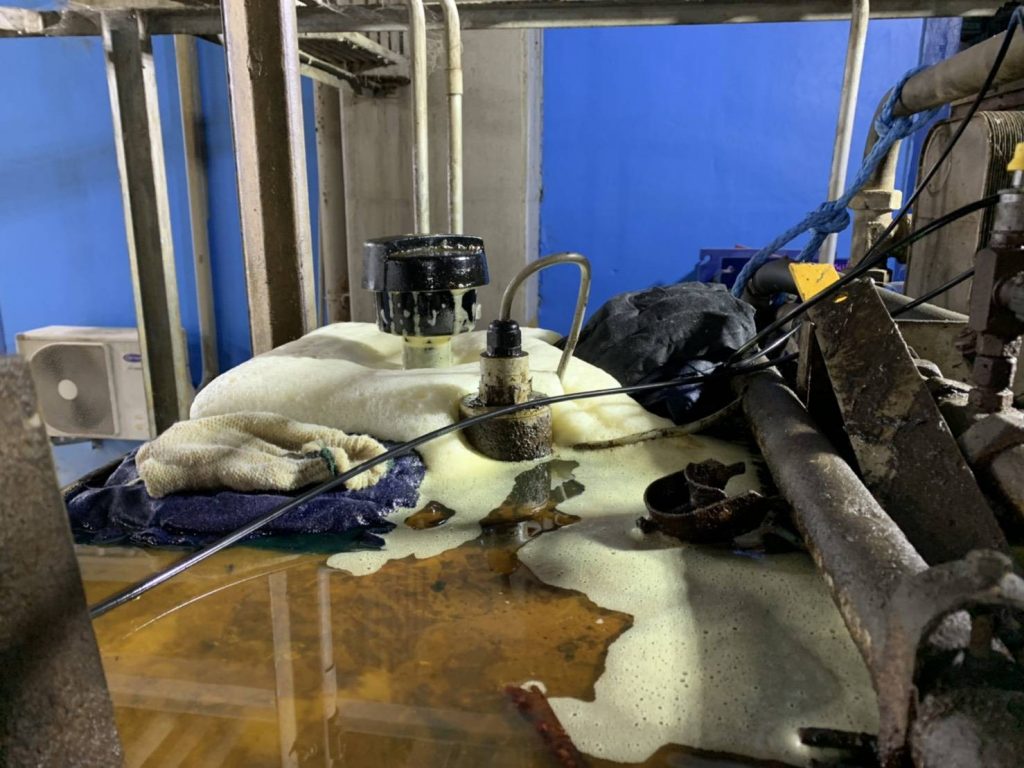
Large Abnormal Air Bubble Foam in the tank.
Air Bubble Foam explodes out of oil reservoir.
Air Bubble Foam still stays at the bottom of oil reservoir after oil was drained out.
Air Bubble Foam expends all over oil reservoir.
Air Bubble Foam at the Manhole tank.
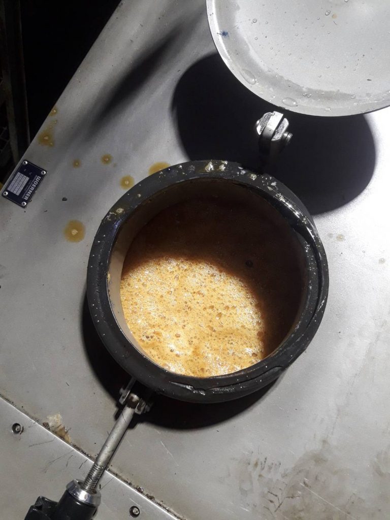
The video shows how bad the Air Bubble Foam flowing out of oil reservoir as Liquid Foam like a milky cream. This Air Bubble Foam does not not dissipate easily and become Stable Foam. This normally caused from Defective Base Oil from refinery. There is no solution to this problem but replacing new base oil.
Free Water at the bottom of oil reservoir is a major cause of Air Foaming in the oil. Air foam will develop into all 3 Air Foaming: Air Bubble, Entrained Air, Dissolved Gases.

Free Water at bottom of oil reservoir is the source of Bacteria & Micro Organism that their growth will generate H2S Hydrogen Sulfide as well as system corrosion in the oil.
When Free Water has been collected at bottom of oil reservoir for a long period of time, oil at the bottom will appear like “Yogurt Oil”. This Water like Yogurt Oil will make it impossible for conventional Vacuum Distillation to remove from oil. This Water Like Yogurt Oil must be pulled out from oil reservoir into DT-100 Free Water Separator prior to any water dehydration of this oil.
Adding Anti Foaming and Dispersant Additives may not solve this Liquid Foam problem. It could backfire the foaming problem to increase surface area so the air foam will adhere one another and become a Liquid Foam as illustrated on the above photos and video.
Sonochemistry – Chemistry of Ultrasound Foaming Acoustic Cavitation in Liquids
When Dissolved Gases expand or implosive collapse in the oil and become larger air foaming such as Entrained Air or Air Bubble, there are a Massive Build-up Potential Energy released from Dissolved gases in to the oil as high oil temperature rising from within the oil molecule. These miniature air foaming in nano size could release as much as 1,000 °F or 538 °C temperature when air foaming is expanding. This explains why most heat exchanger can not cool down the rising oil temperature.
When this potential heating energy is release with high oil pressure in the lubricating oil (Pressure Induced Dieseling (PID) or Pressure Induced Thermal Degradation (PTG), the quick collapse on air foaming is call Micro Dieseling that leads to the Oil Thermal Degradation & Oxidation reaction.
Adding Anti Foaming Additive or Dispersant Additive will not resolve this type of Air Foaming. It will make it worst as the additives will backfire foaming larger air foaming and become Stable Foam. This Air Foaming reconstructs its physical shape into Liquid Foam resulting in higher oil temperature afterward. It will breakdown the Oil Film on metal surface causing Lubrication Failure in the equipment.
These Air Foaming must be under control to minimal by using Degasification of Dissolved Gas และ De-aeration of Entrained Air & Air Bubble to get them out from the oil.
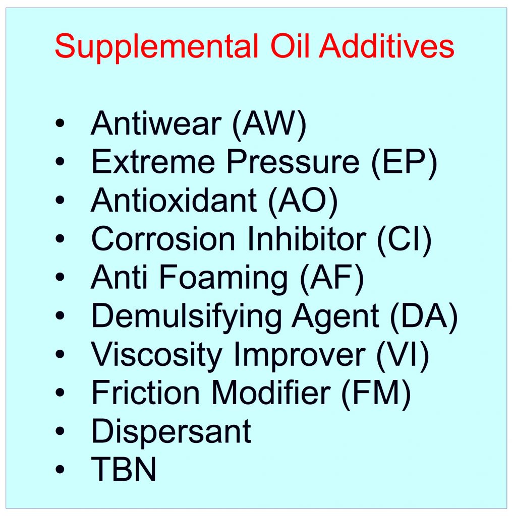
Supplement Oil Additive (SAR) Refortification
Oil Additive Refortification – OilPure has the ability to refortify oil additives that has been depleted or missing due to the inadequate quantity starting from new oil, as well as upgrade the current lubrication to be a premium grade lubrication at a fraction of the cost of new oil.
These Supplemental Oil Additives (SAR) are Anti Wear, Anti Oxidant, Extreme Pressure, Anti Foaming, Demulsifying Agent, Friction Modifier, Tackifier etc. Most new oil has barely minimal amount of oil additives due to the cost competitive. So oil suppliers usually lower the additive amount in order to compete with their rivals. So most new oils have little protection to begin with. After used oil is purified with OilPure equipment, Additive (SAR) can be refortified to enhance the lubricants to be better than new oil quality.
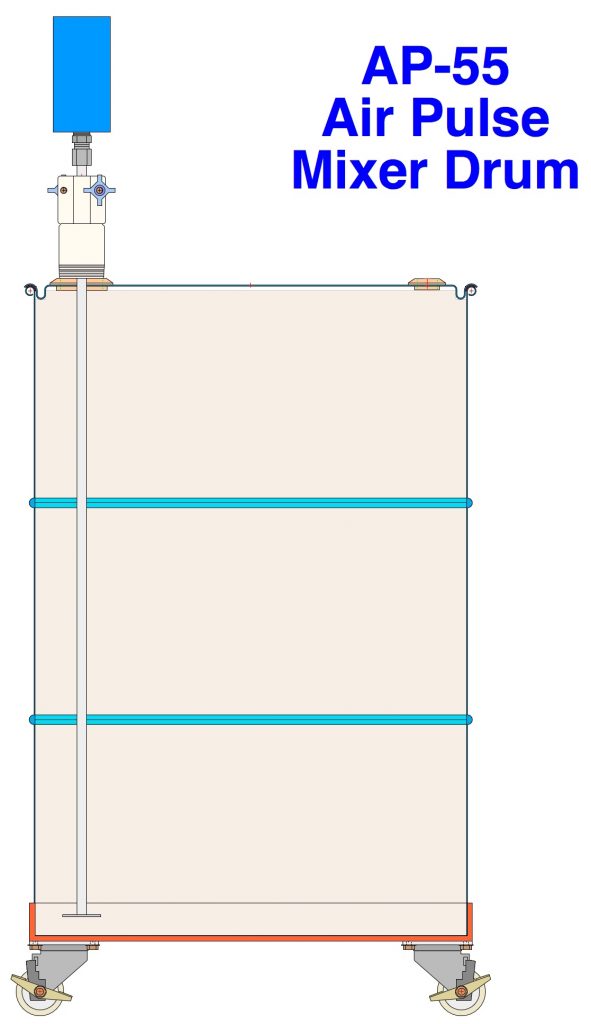
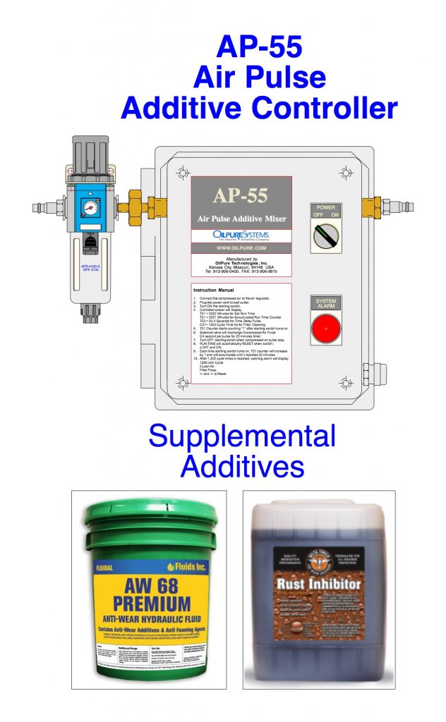
OilPure supplies the Supplemental Additives, AP-55 mixer and additive formula so customer can blend by themselves.
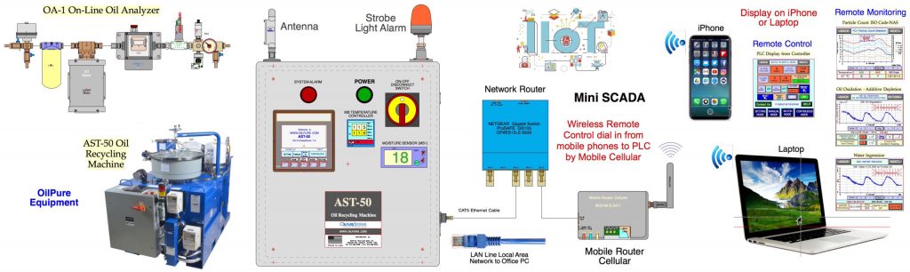
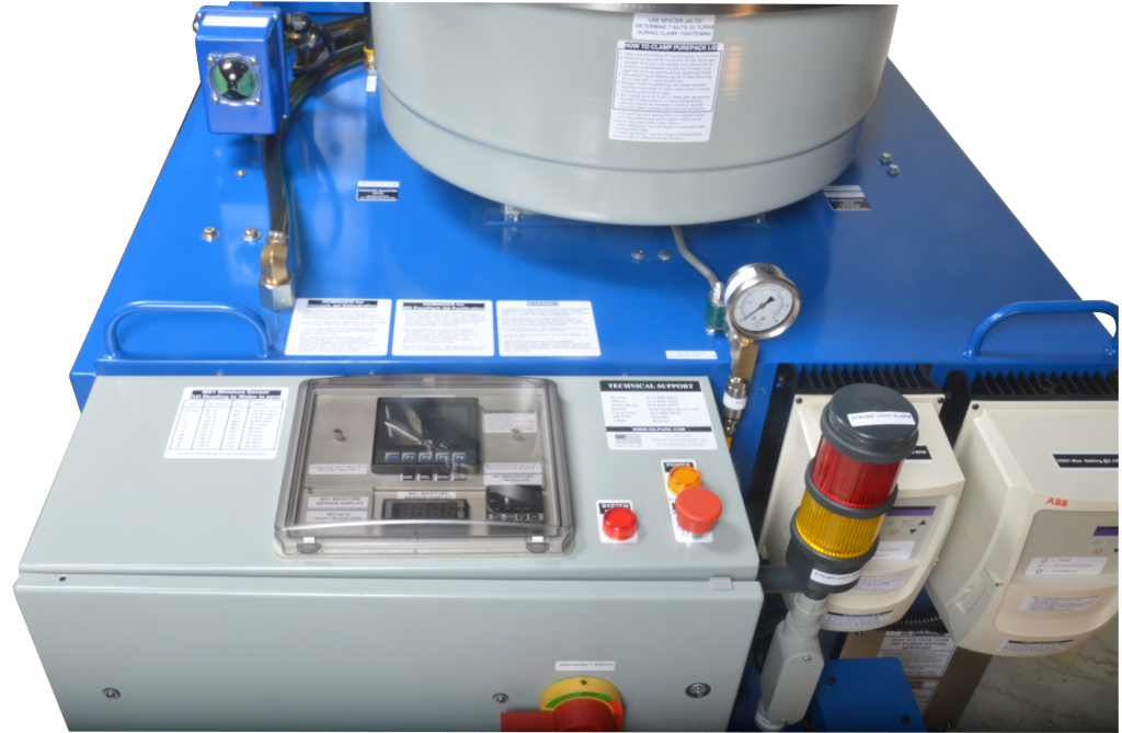
Automation IIOT 4.0 Wireless Communication (Mini SCADA) in OilPure Equipment
OilPure has developed the software program in all oil purifier equipment controller to be the unmanned operation with Remote Control and Remote Monitoring system through a WebMI Code technology that can be used in the web browser with Static IP Address SIMM card for wireless communication protocol. All OilPure equipment can be communicated through smart phone App in both iPhone iOS or Android or browser from PC laptop.
Remote Alarm Monitoring & Alarm Message Sending by Gmail & SMS Text Message
Remote Alarm Monitoring can be accessed by Smart Phone App in both iPhone iOS and Android Operating Systems. Alarm Messages are forwarded by Gmail and SMS Text Message to use smart phones that program has been set in the WebMI. Quality oil information can be sent from On-Line Oil Analyzer directly to the users as well as Machine Condition Monitoring i
Remote Alarm Monitoring can be accessed by Smart Phone App in both iPhone iOS and Android Operating Systems. Alarm Messages are forwarded by Gmail and SMS Text Message to use smart phones that program has been set in the WebMI. Quality oil information can be sent from On-Line Oil Analyzer directly to the users as well as Machine Condition Monitoring in Real Time.
Oil Analysis data is sent directly from PLC server to user smart phones. Most competitors still send their oil data through Corporate Server or CLOUD and allows the IT manager to manage the information to users. This IT process is not reliable and becoming obsoleted as data has to go through so many channels risking default.
Remote Control from Smart Phone App or Browser in PC Laptop with IP Address

User can remotely access their oil purifier equipment and On-Line Oil Analyzer from Smart Phone App to illustrate the PLC display on the phone. User will be aware of his machine and oil purifier condition on a 24 hours Real Time basis.
On-Line Oil Analyzer – Oil Analysis & Machine Condition Monitoring System
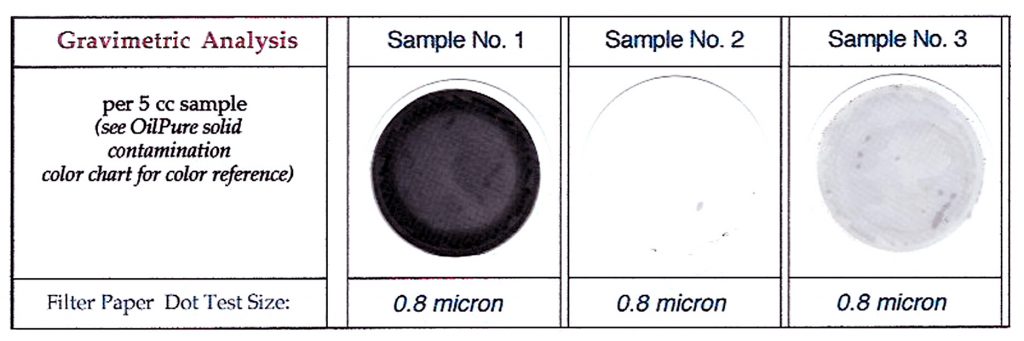
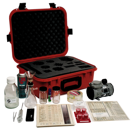
OilPure Portable DOT Test kit for @0.8 Micron Solid Particulate and TAN Test Kit
DOT Test Kit (Gravimetric Analysis)
DOT Test Kit measure solid particulate with Gravimetric Analysis having oil go through a 0.8 micron test paper filter. This is a Qualitative Analysis that is easy to use, easy to interpret the particulate result and more accurate as compared to NAS or ISO Code Particle Count (ISO 4406.)
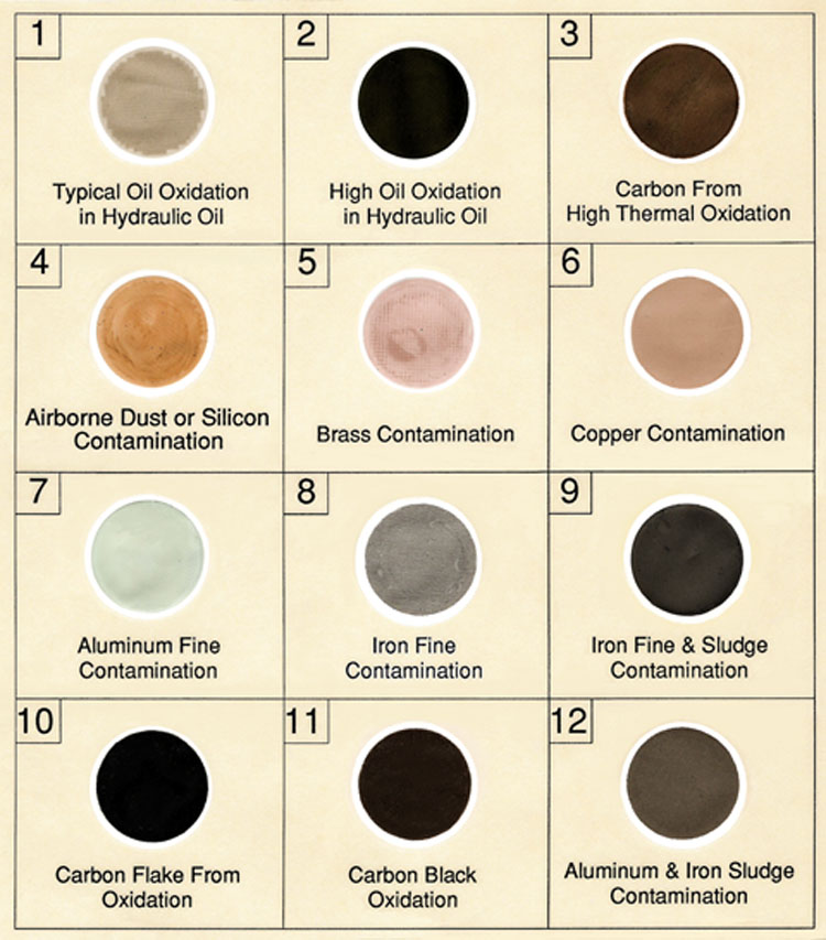
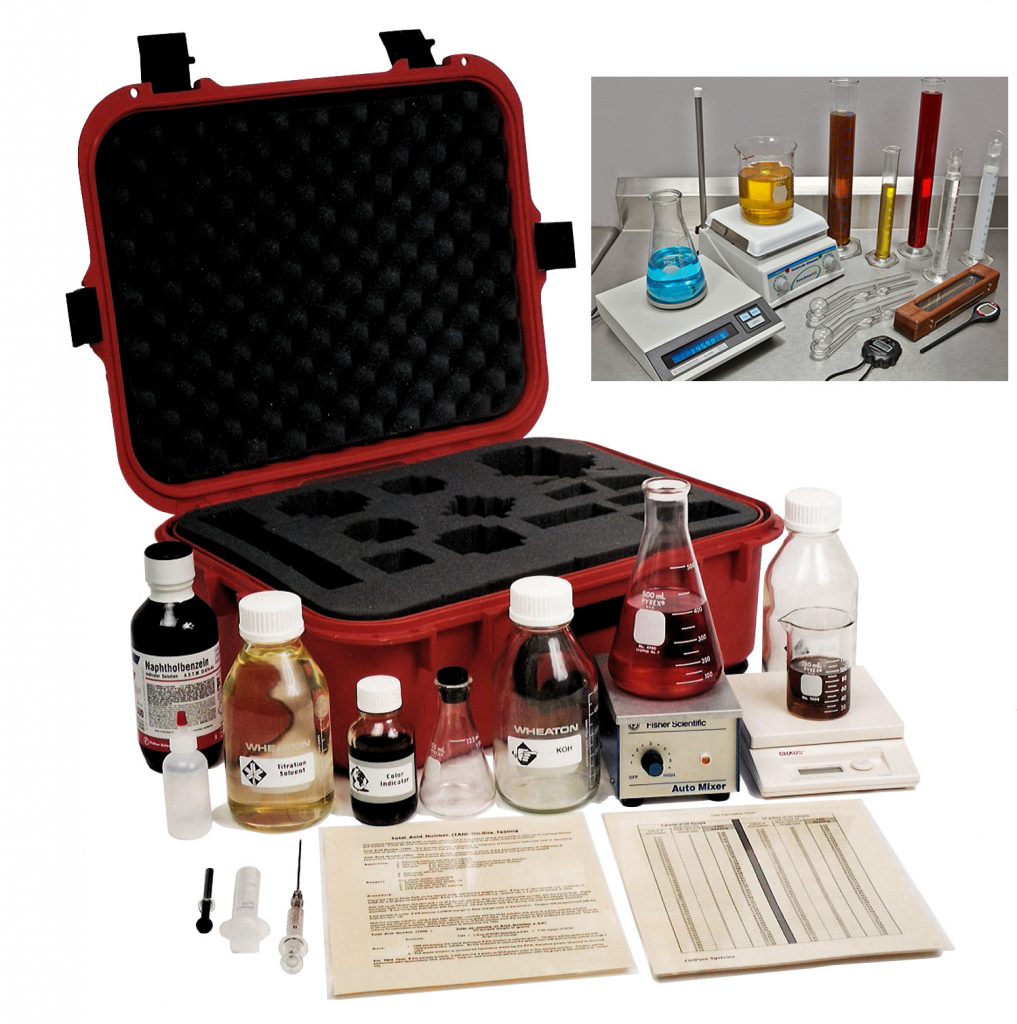
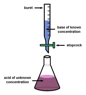
TAN Test Kit (Total Acid Number)
TAN Test Kit measures oil acidity that caused by Oil Oxidation and chemical changes in the oil. TAN reads in mg of KOH per gm unit.
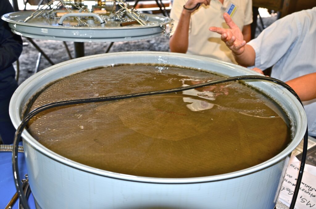
OilPure In-House Oil Reclamation System
Oil user can recycle their used lubricants that control water, solid particulate, oil oxidation, and oil acidity in large machinery such as Paper Machine, Power Generating Turbine, Cold Roll Mill in steel mill that has 2,500 – 5,000 gallons of oil reservoir.
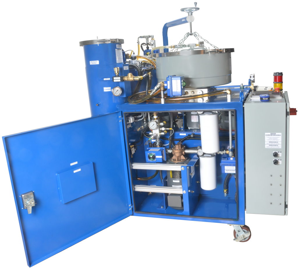
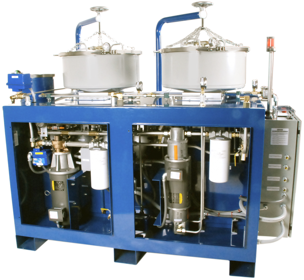
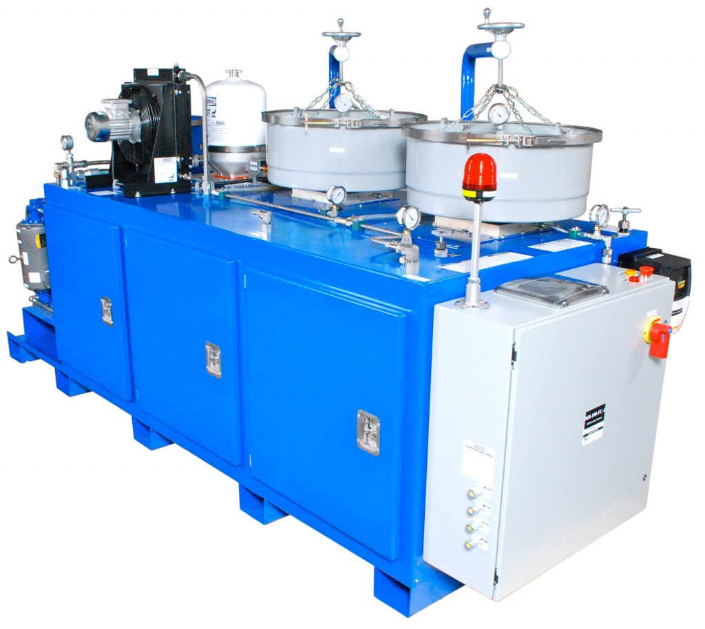
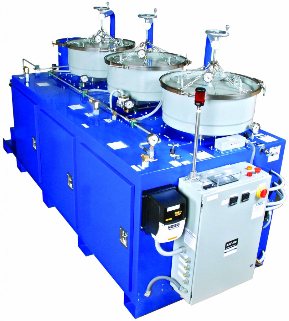
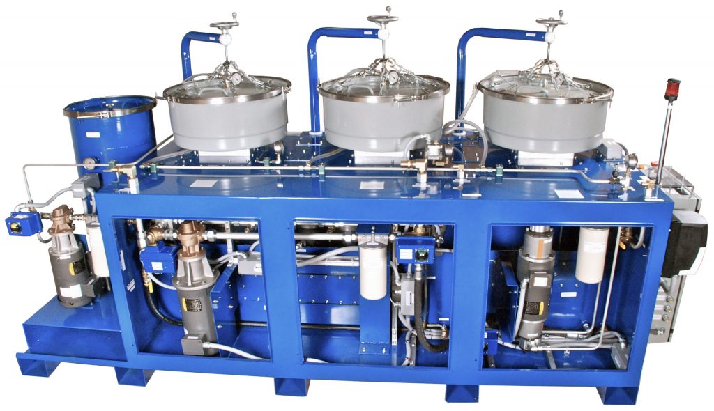
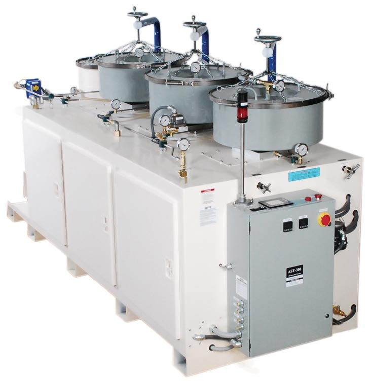
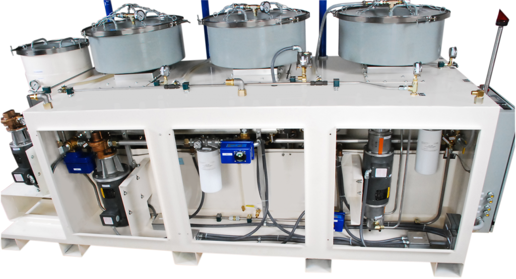
This In-House Oil Reclamation System is fully automated with IIOT4.0, unmanned operation to remove Total Oil Contamination from dirty oil to become a new reusable oil. These OilPure equipment includes AST-50, AST-200, AST-300 and Built-in On-Line Oil Analyzer.
- AST-50 is good for oil reservoir size up to 1,200 gallons with Total Oil Contamination Turnover in 22 days.
- AST-200 is good for oil reservoir size up to 2,500 gallons with Total Oil Contamination Turnover in 22 days.
- AST-300 is good for oil reservoir size up to 4,000 gallons with Total Oil Contamination Turnover in 22 days.
- AST-300 is good for oil reservoir size up to 5,000 gallons with Total Oil Contamination Turnover in 30 days.
- Total Oil Contamination Turnover in 22 days or oil in the reservoir is free of contamination every 22 days.
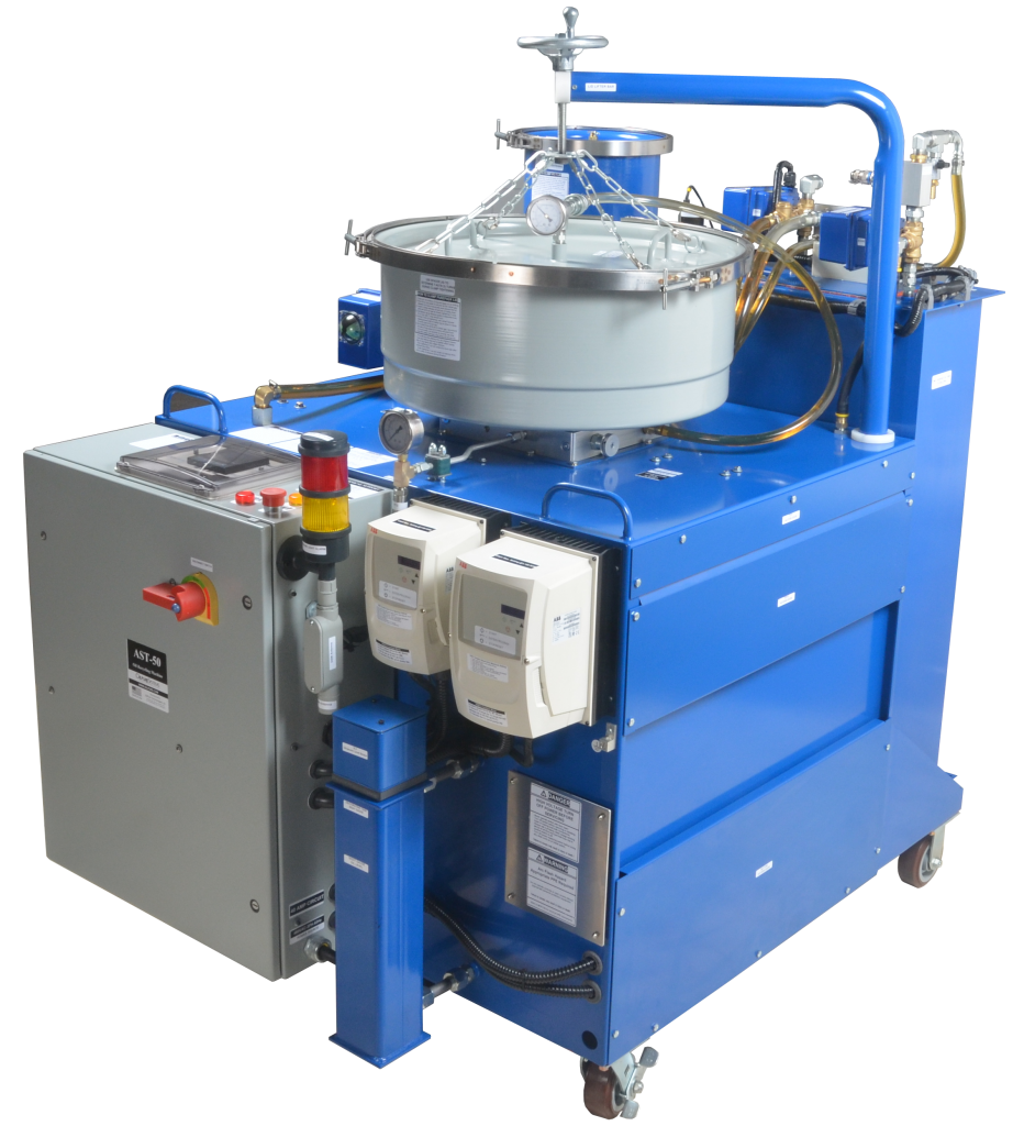
AST-50

AST-200
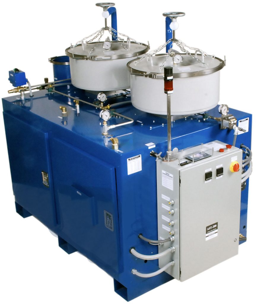
AST-300
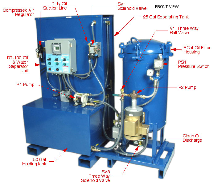
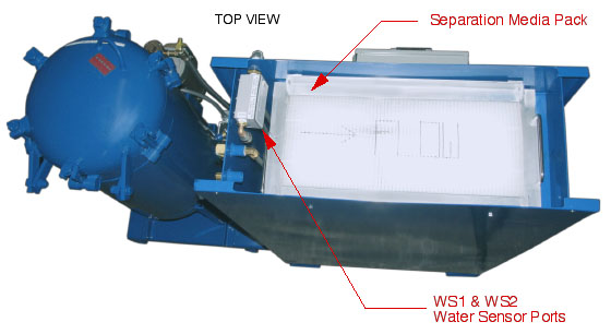
Free Water Separation Technology (Dynamic Separation)
DT-100 Free Water Separator is designed to separate and remove up to 80% Free Water from bottom oil reservoir. Free Water will flow through a Coalescing Pack with Acoustic Ultrasonic Vibration to help split Free Water to bottom of DT-100 tank while oil to floating toward the top of the DT-100 tank.
DT-100 is good for Large Steam Turbine or Paper Machine that have tendency for Free Water breakdown or leakage into the uncontrollable lubricating oil. This Free Water can come from breakdown of heat exchanger, steam escape from Bearing seal, or broken seals. Water will accumulate to bottom of oil reservoir and becomes excessive Free Water. This water problem can be noticed on the presence of Foaming in the oil reservoir.
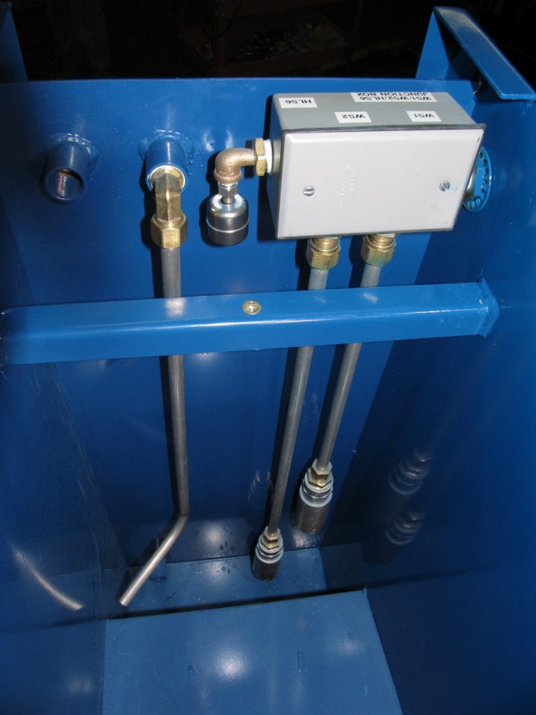
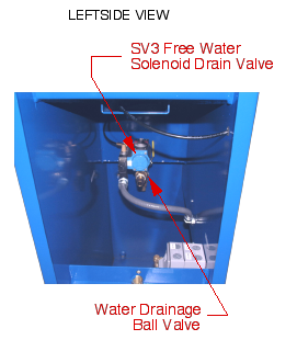
DT-100 can be installed on oil reservoir on a continuous basis as Insurance Policy to monitor excessive Free Water in the oil reservoir. WS1 Water Sensor in DT-100 will detect Free Water layer interface collecting from bottom of oil reservoir and automatically drains water from DT-100 at 20 gallons per hours capacity. DT-100 also counts number of gallon volume of Free Water Drainage and acknowledge the Free Water Ingression Rate from oil reservoir. This Ingreesion Rate is helpful for user to put together a Proactive Preventive System for excessive water.
WS1 Water Sensors detect water & oil interface layer.
WS1 Water Sensors detect water & oil interface layer.
WS1 Dual Water Sensor detects Free Water Layer Interface with Ultrasonic Signal to energize solenoid valve to open water drainage and de-energize solenoid valve to close when water was drained out of the DT-100 on a continuous basis.
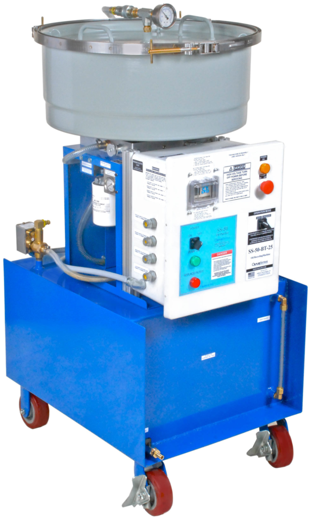
High Speed Centrifuge for Sludge Separator
OilPure small High Speed Centrifuge, TC-8 and TC-4 is designed to separate excessive sludge from cutting oil or quenching oil at 4,000-6,000 rpm. This generate Centrifugal Forces of 3,500 times of Gravity Forces that can separate sludge at 50 micron size.
TC-8 & TC-4 controls oil pressure with VSD Variable Speed Drive on pump motor feed the oil through Jet Turbine Propel Centrifuge that is capable of separating sludge at 10-20 pounds per day.
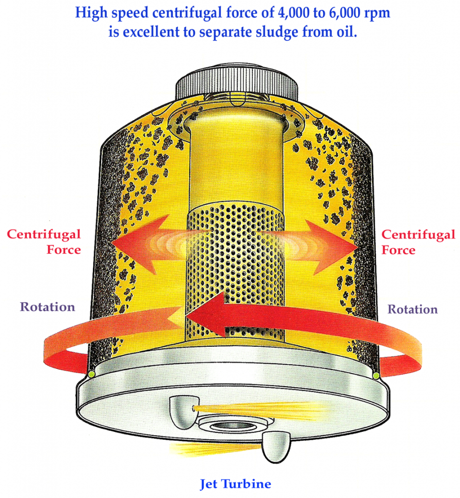
Turbine Jet Centrifuge
10-20 pounds of sludge per day capacity
Filter Cartridge for Pre-Filtration
OilPure Filter Cartridge in FC-1 & FC-4 is a special Air Lock Design that allows dirty oil to flow through filter media, not pressurized through the media as done in conventional cartridge filter. This allows dirty oil to flow upward to top of the filter and create the separation between larger particle sludge and free water to fall to bottom of the filter housing. It is in between a Filtration and Separation having 5-10 times more dirt holding capacity as compared to other filters. Free Water can be drained from bottom of filter housing.
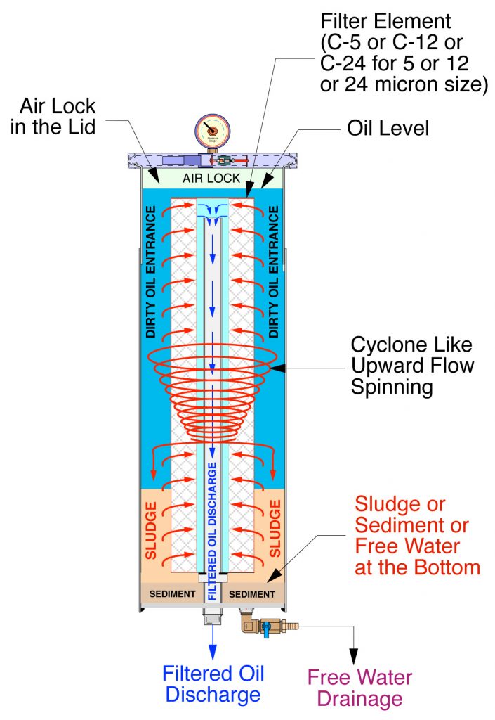
Air Lock Design
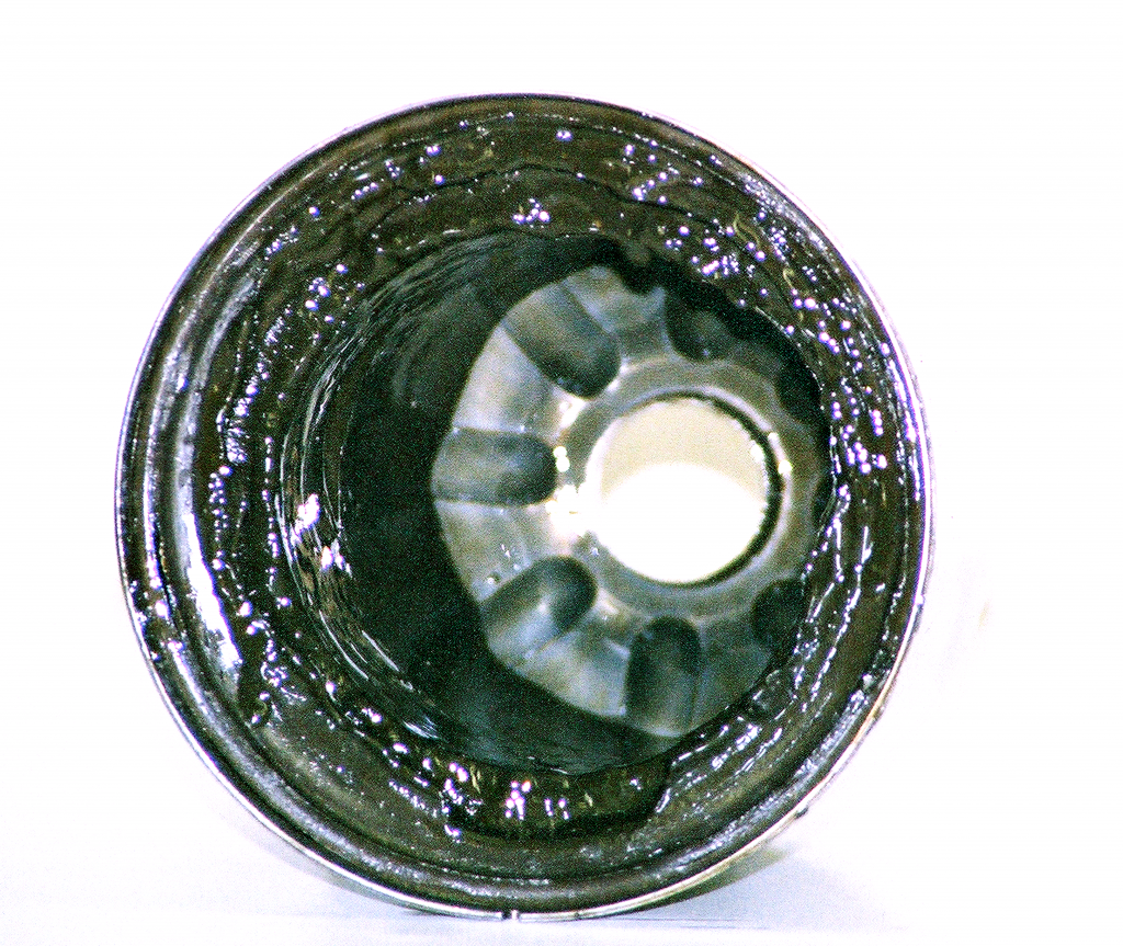
FC-1 Filter Housing
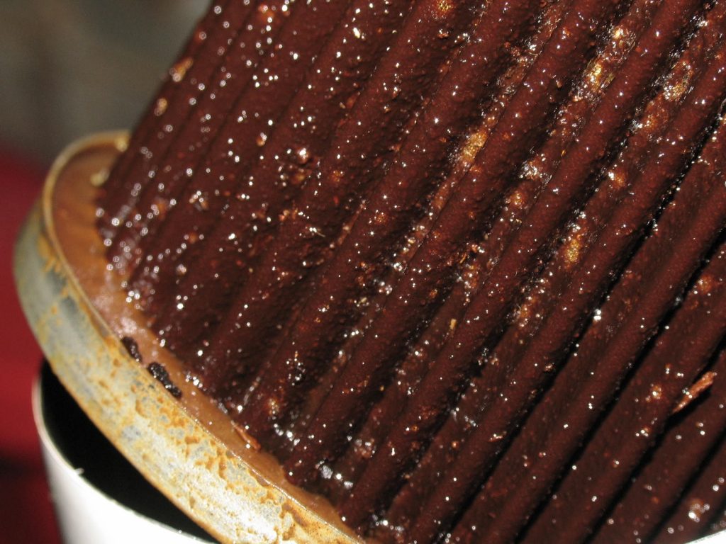
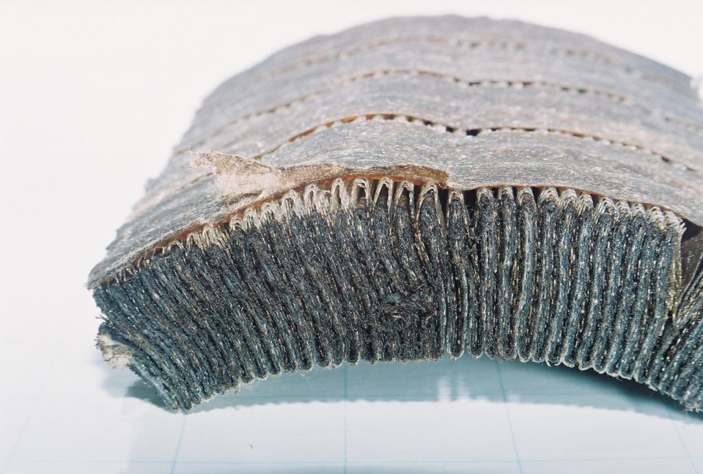
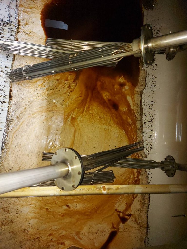
Spent C-5 Filter media with high dirt holding capacity
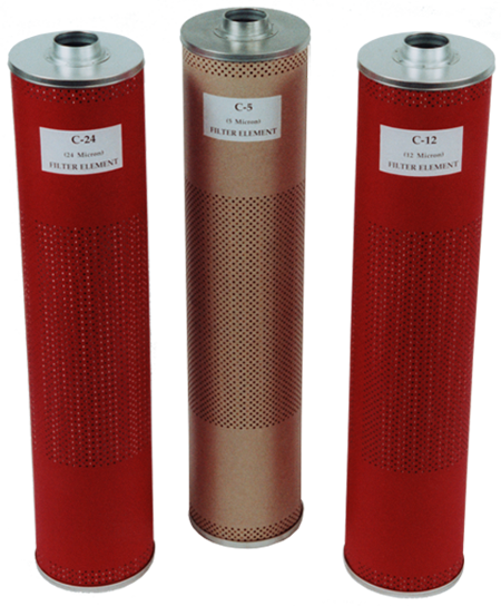
C-5, C-12, C-24 Filter Elements
C Series Filter Elements has three different micron size (Nominal Value) in 5, 12, 24 microns (C-5, C-12, C-24) and design to be a Pre-Filtration with Low Filter Retention for Separation, rather than Filtration. Its filter media is made of Cellulose material that does not generate Electrostatic Charge in the oil. It can handle oil temperature up to 375°F to remove excessive carbon in quenching oil in Heat Treatment Furnace.
© Copyright, August , 2021
Document and information in this website is a proprietary information belonging to OilPure and is not allowed to reveal to public without OilPure consent.